


 |
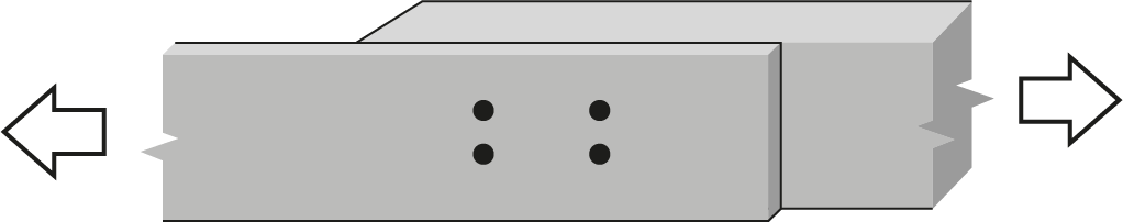
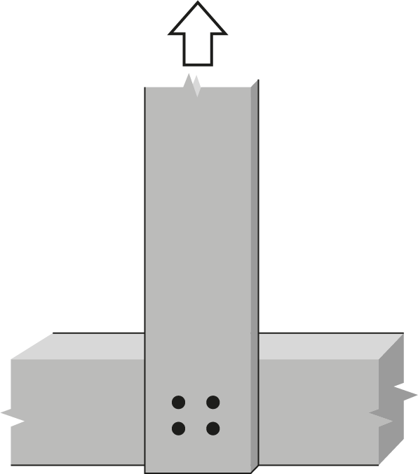
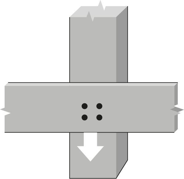
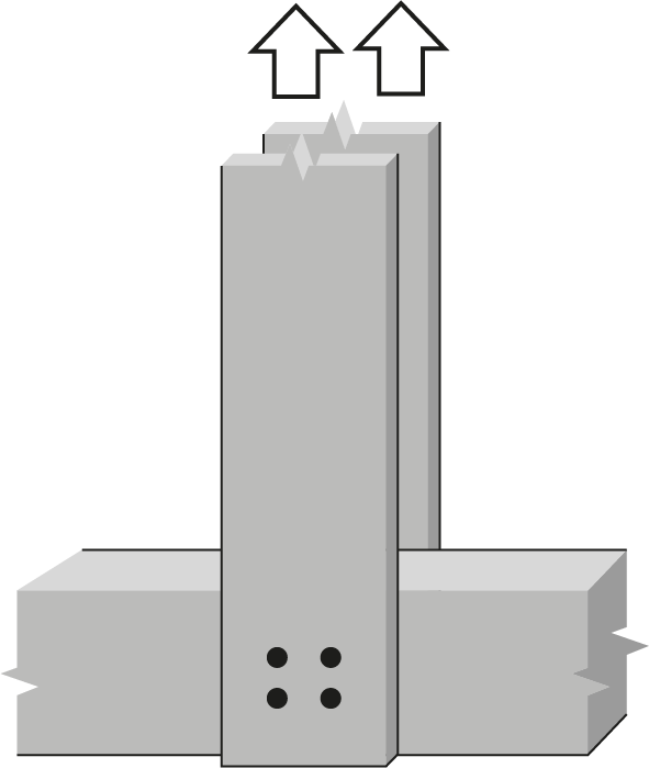
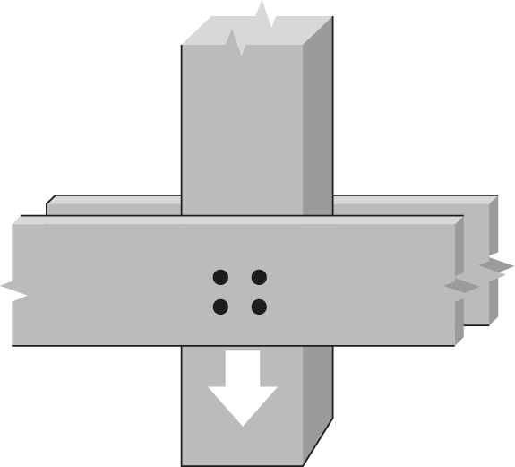
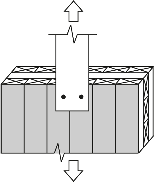
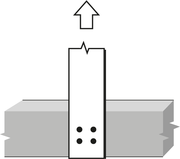
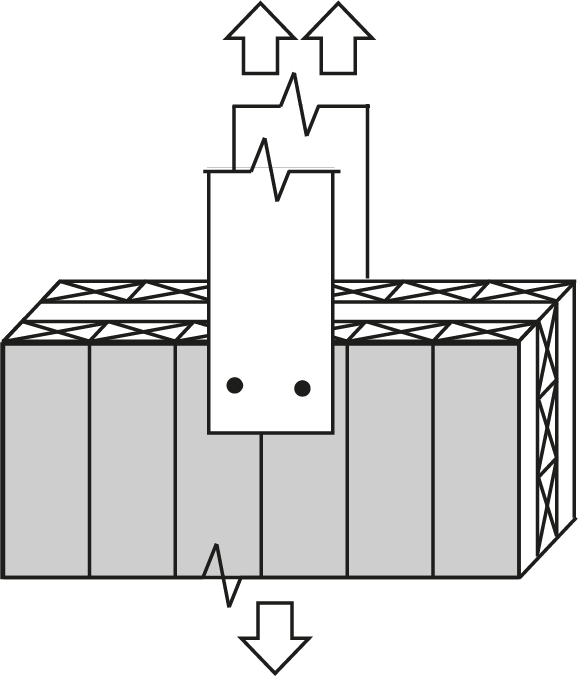
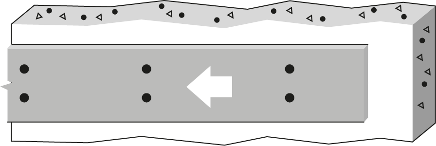
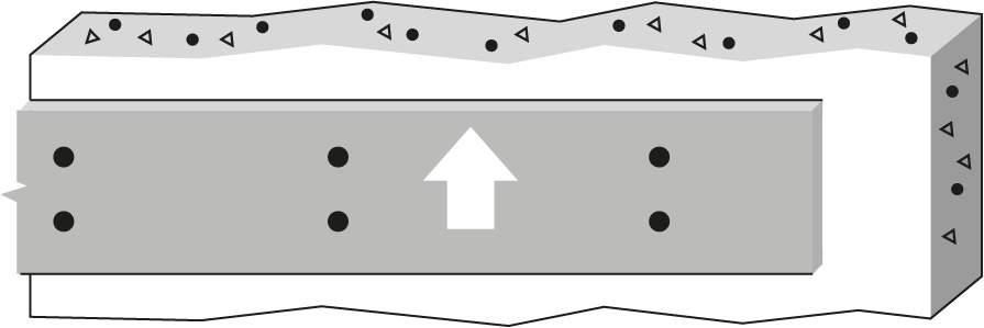
7/8″ Bolt or dowel Double Shear, Spruce-Pine glulam to 6 mm steel plates |
 |
|||||||||||||
| Wood Member | Fastener |
 |
|||||||||||||
|
Thickness (mm) |
Depth (mm) |
No. of rows |
 |
No. of fasteners in a row | |||||||||||
| 2 | 3 | ||||||||||||||
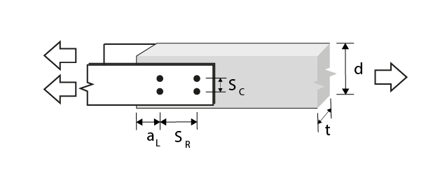
| Bolt spacing in a row taken as the minimum of the loaded end distance3, aL, and the spacing between bolts in a row, SR (mm) | |||||||||||||||
| 89 | 133 | 178 | 222 | 267 | 89 | 133 | 178 | 222 | 267 | ||||||
| 80 | 114 | 1 | 0 | 20.9(R) | 31.4(R) | 41.8(R) | 48.7(c) | 48.7(c) | 31.4(R) | 47.0(R) | 62.7(R) | 73.0(c) | 73.0(c) | ||
| 80 | 228 | 2 | 66.675 | 41.8(R) | 62.7(R) | 82.2(G) | 92.7(G) | 97.4(c) | 62.7(R) | 87.5(G) | 103(G) | 119(G) | 135(G) | ||
| 80 | 228 | 2 | 111.125 | 41.8(R) | 62.7(R) | 83.6(R) | 97.4(c) | 97.4(c) | 62.7(R) | 94.1(R) | 125(R) | 146(c) | 146(c) | ||
| 80 | 266 | 2 | 125 | 41.8(R) | 62.7(R) | 83.6(R) | 97.4(c) | 97.4(c) | 62.7(R) | 94.1(R) | 125(R) | 146(c) | 146(c) | ||
| 130 | 152 | 1 | 0 | 34.0(R) | 51.0(R) | 68.0(R) | 79.1(c) | 79.1(c) | 51.0(R) | 76.4(R) | 102(R) | 119(c) | 119(c) | ||
| 130 | 228 | 2 | 66.675 | 68.0(R) | 102(R) | 134(G) | 151(G) | 158(c) | 102(R) | 142(G) | 168(G) | 193(G) | 219(G) | ||
| 130 | 228 | 2 | 111.125 | 68.0(R) | 102(R) | 136(R) | 158(c) | 158(c) | 102(R) | 153(R) | 204(R) | 237(c) | 237(c) | ||
| 130 | 266 | 2 | 125 | 68.0(R) | 102(R) | 136(R) | 158(c) | 158(c) | 102(R) | 153(R) | 204(R) | 237(c) | 237(c) | ||
| 175 | 190 | 1 | 0 | 45.7(R) | 68.6(R) | 91.5(R) | 93.3(g) | 93.3(g) | 68.6(R) | 103(R) | 137(R) | 140(g) | 140(g) | ||
| 175 | 228 | 2 | 66.675 | 91.5(R) | 137(R) | 180(G) | 187(g) | 187(g) | 137(R) | 191(G) | 226(G) | 260(G) | 280(g) | ||
| 175 | 228 | 2 | 111.125 | 91.5(R) | 137(R) | 183(R) | 187(g) | 187(g) | 137(R) | 206(R) | 274(R) | 280(g) | 280(g) | ||
| 175 | 266 | 2 | 125 | 91.5(R) | 137(R) | 183(R) | 187(g) | 187(g) | 137(R) | 206(R) | 274(R) | 280(g) | 280(g) | ||
| 215 | 266 | 1 | 0 | 56.2(R) | 84.3(R) | 93.3(g) | 93.3(g) | 93.3(g) | 84.3(R) | 126(R) | 140(g) | 140(g) | 140(g) | ||
| 215 | 266 | 2 | 66.675 | 112(R) | 169(R) | 187(g) | 187(g) | 187(g) | 169(R) | 235(G) | 277(G) | 280(g) | 280(g) | ||
| 215 | 266 | 2 | 111.125 | 112(R) | 169(R) | 187(g) | 187(g) | 187(g) | 169(R) | 253(R) | 280(g) | 280(g) | 280(g) | ||
| 215 | 266 | 2 | 125 | 112(R) | 169(R) | 187(g) | 187(g) | 187(g) | 169(R) | 253(R) | 280(g) | 280(g) | 280(g) | ||
| 265 | 342 | 1 | 0 | 69.3(R) | 93.3(g) | 93.3(g) | 93.3(g) | 93.3(g) | 104(R) | 140(g) | 140(g) | 140(g) | 140(g) | ||
| 265 | 342 | 2 | 66.675 | 139(R) | 187(g) | 187(g) | 187(g) | 187(g) | 208(R) | 280(g) | 280(g) | 280(g) | 280(g) | ||
| 265 | 342 | 2 | 111.125 | 139(R) | 187(g) | 187(g) | 187(g) | 187(g) | 208(R) | 280(g) | 280(g) | 280(g) | 280(g) | ||
| 265 | 342 | 2 | 125 | 139(R) | 187(g) | 187(g) | 187(g) | 187(g) | 208(R) | 280(g) | 280(g) | 280(g) | 280(g) | ||
| 315 | 380 | 1 | 0 | 82.3(R) | 93.3(g) | 93.3(g) | 93.3(g) | 93.3(g) | 123(R) | 140(g) | 140(g) | 140(g) | 140(g) | ||
| 315 | 380 | 2 | 66.675 | 165(R) | 187(g) | 187(g) | 187(g) | 187(g) | 247(R) | 280(g) | 280(g) | 280(g) | 280(g) | ||
| 315 | 380 | 2 | 111.125 | 165(R) | 187(g) | 187(g) | 187(g) | 187(g) | 247(R) | 280(g) | 280(g) | 280(g) | 280(g) | ||
| 315 | 380 | 2 | 125 | 165(R) | 187(g) | 187(g) | 187(g) | 187(g) | 247(R) | 280(g) | 280(g) | 280(g) | 280(g) | ||
|
Notes:
|
. | ||||||||||||||