


 |
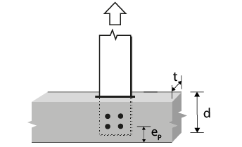
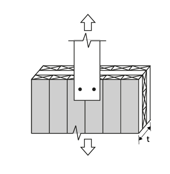
6 mm Steel plate to CLT | |||||
|
CLT thickness t (mm) |
Bolt or dowel diameter (in) |
 |
||||
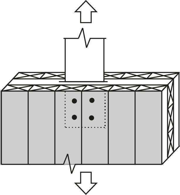
| Type 7 (single shear) | ||||||
 |
||||||
| CLT grade | ||||||
| E2 and V1 | E1 and V2 | E3 | ||||
| 105 (3 ply) | 1/2 | 8.07(g) | 7.48(g) | 6.84(g) | ||
| 105 (3 ply) | 5/8 | 12.4(g) | 11.5(g) | 10.5(g) | ||
| 105 (3 ply) | 3/4 | 17.5(g) | 16.2(g) | 14.8(g) | ||
| 105 (3 ply) | 7/8 | 23.4(g) | 21.6(g) | 19.8(g) | ||
| 105 (3 ply) | 1 | 29.9(g) | 27.7(g) | 25.1(b) | ||
| 175 (5 ply) | 1/2 | 8.07(g) | 7.48(g) | 6.84(g) | ||
| 175 (5 ply) | 5/8 | 12.4(g) | 11.5(g) | 10.5(g) | ||
| 175 (5 ply) | 3/4 | 17.5(g) | 16.2(g) | 14.8(g) | ||
| 175 (5 ply) | 7/8 | 23.4(g) | 21.6(g) | 19.8(g) | ||
| 175 (5 ply) | 1 | 29.9(g) | 27.7(g) | 25.3(g) | ||
| 245 (7 ply) | 1/2 | 8.07(g) | 7.48(g) | 6.84(g) | ||
| 245 (7 ply) | 5/8 | 12.4(g) | 11.5(g) | 10.5(g) | ||
| 245 (7 ply) | 3/4 | 17.5(g) | 16.2(g) | 14.8(g) | ||
| 245 (7 ply) | 7/8 | 23.4(g) | 21.6(g) | 19.8(g) | ||
| 245 (7 ply) | 1 | 29.9(g) | 27.7(g) | 25.3(g) | ||
| 315 (9 ply) | 1/2 | 8.07(g) | 7.48(g) | 6.84(g) | ||
| 315 (9 ply) | 5/8 | 12.4(g) | 11.5(g) | 10.5(g) | ||
| 315 (9 ply) | 3/4 | 17.5(g) | 16.2(g) | 14.8(g) | ||
| 315 (9 ply) | 7/8 | 23.4(g) | 21.6(g) | 19.8(g) | ||
| 315 (9 ply) | 1 | 29.9(g) | 27.7(g) | 25.3(g) | ||
|
Notes:
|
||||||