


 |
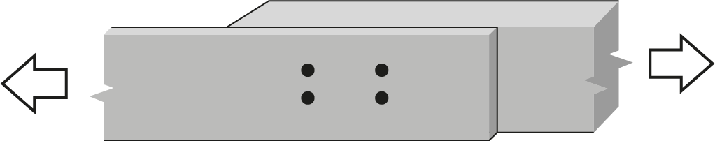
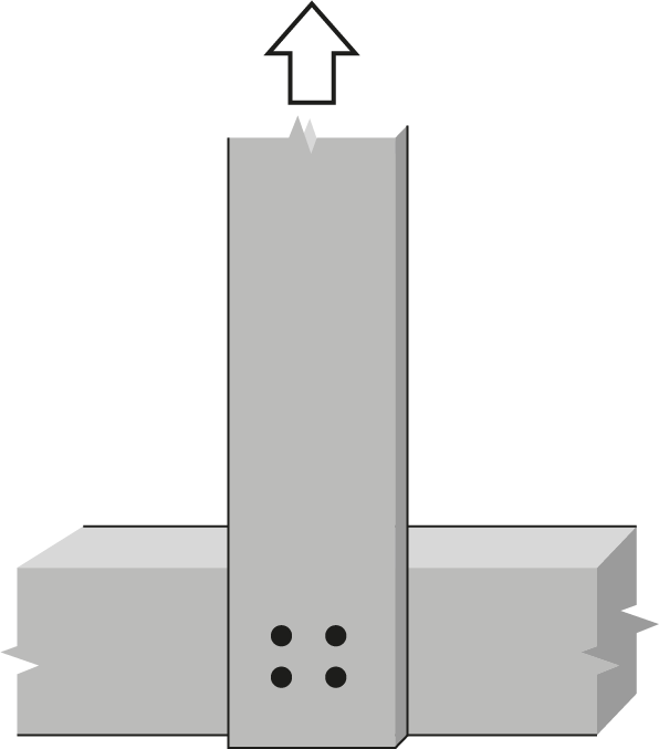
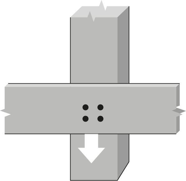
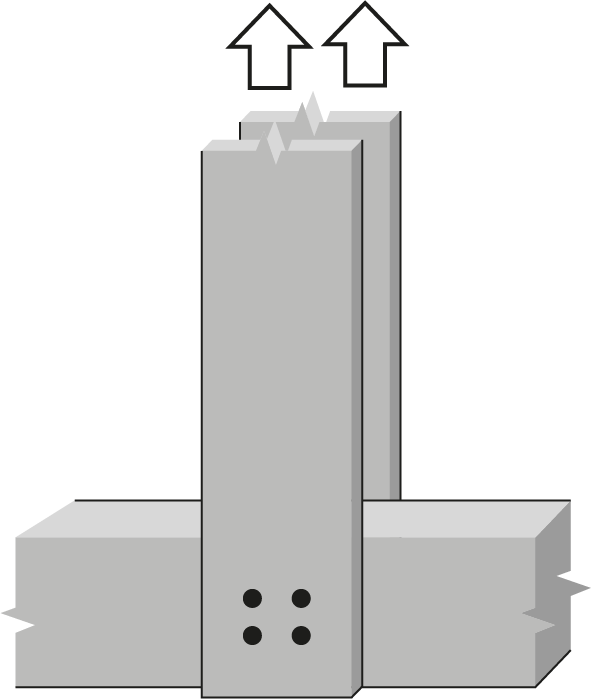
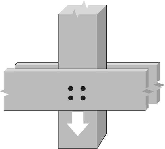
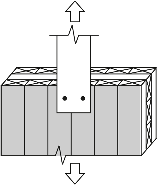
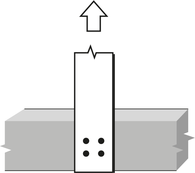
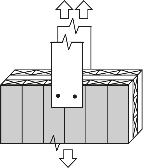
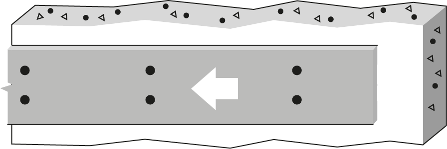
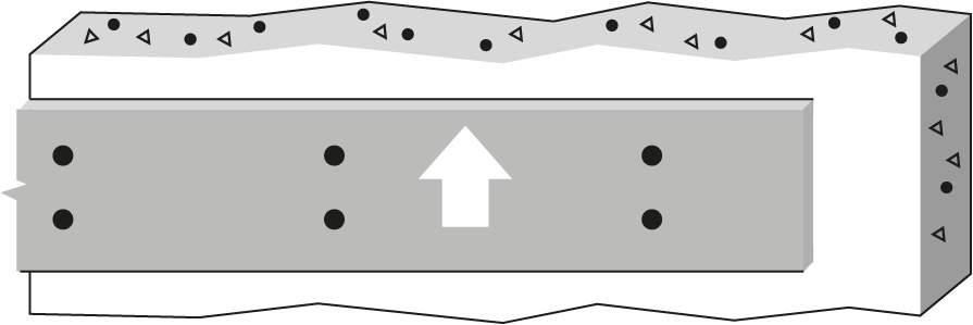
1″ Bolt or dowel Double Shear, Spruce-Pine glulam to 6 mm steel plates |
 |
|||||||||||||
| Wood Member | Fastener |
 |
|||||||||||||
|
Thickness (mm) |
Depth (mm) |
No. of rows |
 |
No. of fasteners in a row | |||||||||||
| 2 | 3 | ||||||||||||||
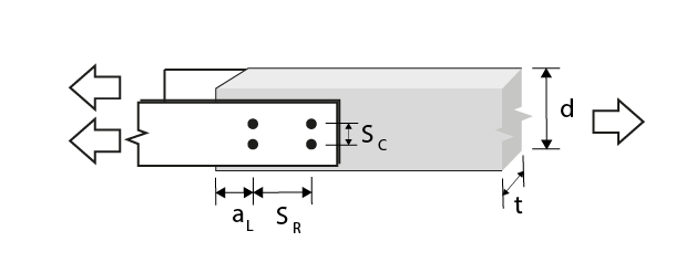
| Bolt spacing in a row taken as the minimum of the loaded end distance3, aL, and the spacing between bolts in a row, SR (mm) | |||||||||||||||
| 102 | 152 | 203 | 254 | 305 | 102 | 152 | 203 | 254 | 305 | ||||||
| 80 | 114 | 1 | 0 | 23.9(R) | 35.8(R) | 47.8(R) | 53.4(c) | 53.4(c) | 35.8(R) | 53.8(R) | 71.7(R) | 80.0(c) | 80.0(c) | ||
| 80 | 228 | 2 | 76.2 | 47.8(R) | 71.7(R) | 94.3(G) | 106(G) | 107(c) | 71.7(R) | 100(G) | 118(G) | 136(G) | 154(G) | ||
| 80 | 266 | 2 | 125 | 47.8(R) | 71.7(R) | 95.6(R) | 107(c) | 107(c) | 71.7(R) | 108(R) | 143(R) | 160(c) | 160(c) | ||
| 80 | 266 | 2 | 125 | 47.8(R) | 71.7(R) | 95.6(R) | 107(c) | 107(c) | 71.7(R) | 108(R) | 143(R) | 160(c) | 160(c) | ||
| 130 | 152 | 1 | 0 | 38.8(R) | 58.2(R) | 77.7(R) | 86.7(c) | 86.7(c) | 58.2(R) | 87.4(R) | 116(R) | 130(c) | 130(c) | ||
| 130 | 228 | 2 | 76.2 | 77.7(R) | 116(R) | 153(G) | 173(G) | 173(c) | 116(R) | 163(G) | 192(G) | 221(G) | 250(G) | ||
| 130 | 266 | 2 | 125 | 77.7(R) | 116(R) | 155(R) | 173(c) | 173(c) | 116(R) | 175(R) | 233(R) | 260(c) | 260(c) | ||
| 130 | 266 | 2 | 125 | 77.7(R) | 116(R) | 155(R) | 173(c) | 173(c) | 116(R) | 175(R) | 233(R) | 260(c) | 260(c) | ||
| 175 | 190 | 1 | 0 | 52.3(R) | 78.4(R) | 105(R) | 117(c) | 117(c) | 78.4(R) | 118(R) | 157(R) | 175(c) | 175(c) | ||
| 175 | 228 | 2 | 76.2 | 105(R) | 157(R) | 206(G) | 232(G) | 233(c) | 157(R) | 219(G) | 258(G) | 298(G) | 337(G) | ||
| 175 | 266 | 2 | 125 | 105(R) | 157(R) | 209(R) | 233(c) | 233(c) | 157(R) | 235(R) | 314(R) | 350(c) | 350(c) | ||
| 175 | 266 | 2 | 125 | 105(R) | 157(R) | 209(R) | 233(c) | 233(c) | 157(R) | 235(R) | 314(R) | 350(c) | 350(c) | ||
| 215 | 266 | 1 | 0 | 64.2(R) | 96.3(R) | 119(g) | 119(g) | 119(g) | 96.3(R) | 144(R) | 179(g) | 179(g) | 179(g) | ||
| 215 | 266 | 2 | 76.2 | 128(R) | 193(R) | 239(g) | 239(g) | 239(g) | 193(R) | 269(G) | 318(G) | 358(g) | 358(g) | ||
| 215 | 266 | 2 | 125 | 128(R) | 193(R) | 239(g) | 239(g) | 239(g) | 193(R) | 289(R) | 358(g) | 358(g) | 358(g) | ||
| 215 | 266 | 2 | 125 | 128(R) | 193(R) | 239(g) | 239(g) | 239(g) | 193(R) | 289(R) | 358(g) | 358(g) | 358(g) | ||
| 265 | 342 | 1 | 0 | 79.2(R) | 119(R) | 119(g) | 119(g) | 119(g) | 119(R) | 178(R) | 179(g) | 179(g) | 179(g) | ||
| 265 | 342 | 2 | 76.2 | 158(R) | 237(R) | 239(g) | 239(g) | 239(g) | 237(R) | 332(G) | 358(g) | 358(g) | 358(g) | ||
| 265 | 342 | 2 | 125 | 158(R) | 237(R) | 239(g) | 239(g) | 239(g) | 237(R) | 356(R) | 358(g) | 358(g) | 358(g) | ||
| 265 | 342 | 2 | 125 | 158(R) | 237(R) | 239(g) | 239(g) | 239(g) | 237(R) | 356(R) | 358(g) | 358(g) | 358(g) | ||
| 315 | 380 | 1 | 0 | 94.1(R) | 119(g) | 119(g) | 119(g) | 119(g) | 141(R) | 179(g) | 179(g) | 179(g) | 179(g) | ||
| 315 | 380 | 2 | 76.2 | 188(R) | 239(g) | 239(g) | 239(g) | 239(g) | 282(R) | 358(g) | 358(g) | 358(g) | 358(g) | ||
| 315 | 380 | 2 | 125 | 188(R) | 239(g) | 239(g) | 239(g) | 239(g) | 282(R) | 358(g) | 358(g) | 358(g) | 358(g) | ||
| 315 | 380 | 2 | 125 | 188(R) | 239(g) | 239(g) | 239(g) | 239(g) | 282(R) | 358(g) | 358(g) | 358(g) | 358(g) | ||
|
Notes:
|
. | ||||||||||||||