


 |
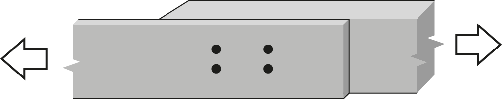
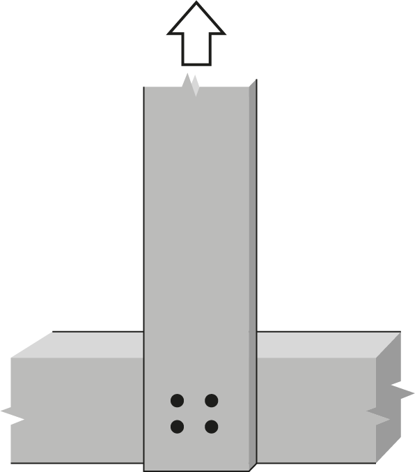
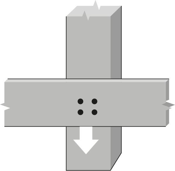
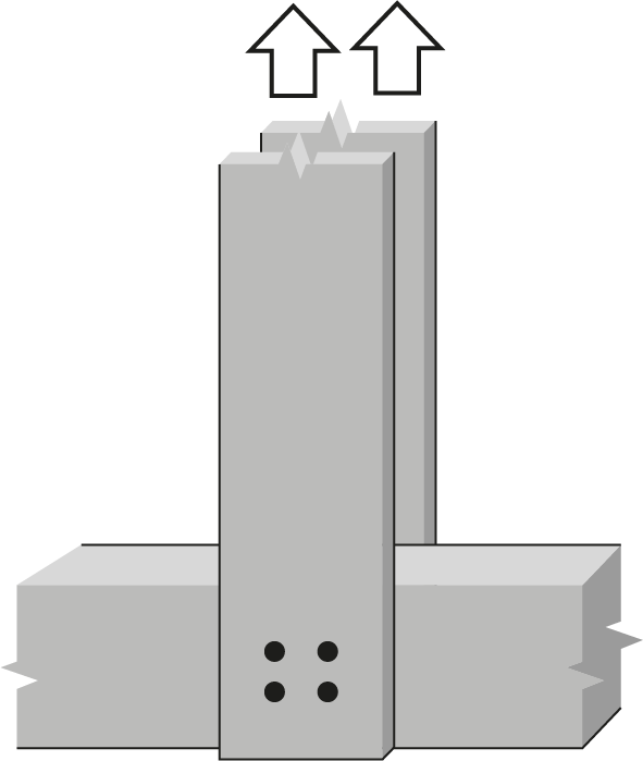
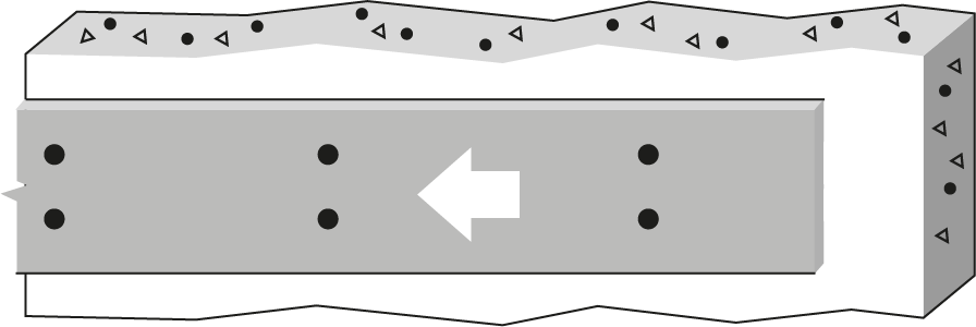
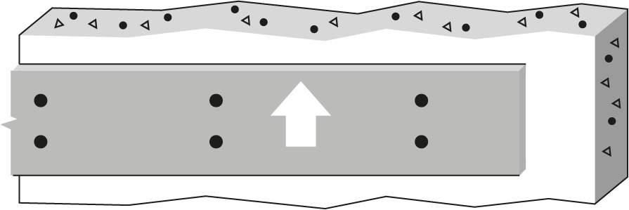
1/2″ Bolt or dowel Single Shear, Northern lumber to 6mm steel plates |
 |
|||||||||||||
| Wood Member | Fastener |
 |
|||||||||||||
|
Thickness (mm) |
Depth (mm) |
No. of rows |
 |
No. of fasteners in a row | |||||||||||
| 2 | 3 | ||||||||||||||
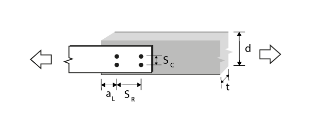
| Bolt spacing in a row taken as the minimum of the loaded end distance3, aL, and the spacing between bolts in a row, SR (mm) | |||||||||||||||
| 51 | 76 | 102 | 127 | 152 | 51 | 76 | 102 | 127 | 152 | ||||||
| 38 | 89 | 1 | 0 | 2.74(R) | 4.11(R) | 5.48(R) | 6.85(R) | 8.22(R) | 4.11(R) | 6.17(R) | 8.22(R) | 10.3(R) | 12.3(R) | ||
| 38 | 140 | 2 | 38.1 | 5.23(G) | 6.60(G) | 7.97(G) | 9.34(G) | 10.7(G) | 6.60(G) | 8.66(G) | 10.7(G) | 12.8(G) | 14.8(G) | ||
| 38 | 140 | 2 | 63.5 | 5.48(R) | 8.22(R) | 10.7(G) | 12.0(G) | 13.4(G) | 8.22(R) | 11.4(G) | 13.4(G) | 15.5(G) | 17.5(G) | ||
| 38 | 184 | 2 | 88.9 | 5.48(R) | 8.22(R) | 11.0(R) | 13.7(R) | 16.1(G) | 8.22(R) | 12.3(R) | 16.1(G) | 18.2(G) | 20.2(G) | ||
| 38 | 184 | 3 | 38.1 | 7.72(G) | 9.09(G) | 10.5(G) | 11.8(G) | 13.2(G) | 9.09(G) | 11.1(G) | 13.2(G) | 15.3(G) | 17.3(G) | ||
| 38 | 235 | 3 | 62.5 | 8.22(R) | 12.3(R) | 15.7(G) | 17.0(G) | 18.4(G) | 12.3(R) | 16.3(G) | 18.4(G) | 20.4(G) | 22.5(G) | ||
| 89 | 89 | 1 | 0 | 6.42(R) | 9.63(R) | 12.8(R) | 14.4(g) | 14.4(g) | 9.63(R) | 14.4(R) | 19.3(R) | 21.6(g) | 21.6(g) | ||
| 89 | 140 | 2 | 38.1 | 12.2(G) | 15.5(G) | 18.7(G) | 21.9(G) | 25.1(G) | 15.5(G) | 20.3(G) | 25.1(G) | 29.9(G) | 34.7(G) | ||
| 89 | 140 | 2 | 63.5 | 12.8(R) | 19.3(R) | 25.0(G) | 28.2(G) | 28.8(g) | 19.3(R) | 26.6(G) | 31.4(G) | 36.2(G) | 41.0(G) | ||
| 89 | 184 | 2 | 88.9 | 12.8(R) | 19.3(R) | 25.7(R) | 28.8(g) | 28.8(g) | 19.3(R) | 28.9(R) | 37.7(G) | 42.6(G) | 43.2(g) | ||
| 89 | 184 | 3 | 38.1 | 18.1(G) | 21.3(G) | 24.5(G) | 27.7(G) | 30.9(G) | 21.3(G) | 26.1(G) | 30.9(G) | 35.7(G) | 40.5(G) | ||
| 89 | 235 | 3 | 62.5 | 19.3(R) | 28.9(R) | 36.7(G) | 39.9(G) | 43.1(G) | 28.9(R) | 38.3(G) | 43.1(G) | 47.9(G) | 52.7(G) | ||
| 140 | 140 | 1 | 0 | 7.77(R) | 11.6(R) | 14.4(g) | 14.4(g) | 14.4(g) | 11.6(R) | 17.5(R) | 21.6(g) | 21.6(g) | 21.6(g) | ||
| 140 | 140 | 2 | 38.1 | 13.5(G) | 17.4(G) | 21.3(G) | 25.1(G) | 28.8(g) | 17.4(G) | 23.2(G) | 29.0(G) | 34.9(G) | 40.7(G) | ||
| 140 | 140 | 2 | 63.5 | 15.5(R) | 23.3(R) | 27.5(G) | 28.8(g) | 28.8(g) | 23.3(R) | 29.4(G) | 35.3(G) | 41.1(G) | 43.2(g) | ||
| 140 | 191 | 2 | 88.9 | 15.5(R) | 23.3(R) | 28.8(g) | 28.8(g) | 28.8(g) | 23.3(R) | 34.9(R) | 41.5(G) | 43.2(g) | 43.2(g) | ||
| 140 | 191 | 3 | 38.1 | 19.2(G) | 23.1(G) | 27.0(G) | 30.9(G) | 34.8(G) | 23.1(G) | 28.9(G) | 34.8(G) | 40.6(G) | 46.4(G) | ||
| 140 | 191 | 3 | 62.5 | 23.3(R) | 34.9(R) | 39.0(G) | 42.8(G) | 43.2(g) | 34.9(R) | 40.9(G) | 46.7(G) | 52.5(G) | 55.5(T) | ||
| 191 | 140 | 1 | 0 | 10.6(R) | 14.4(g) | 14.4(g) | 14.4(g) | 14.4(g) | 15.9(R) | 21.6(g) | 21.6(g) | 21.6(g) | 21.6(g) | ||
| 191 | 140 | 2 | 38.1 | 18.4(G) | 23.7(G) | 28.8(g) | 28.8(g) | 28.8(g) | 23.7(G) | 31.7(G) | 39.6(G) | 43.2(g) | 43.2(g) | ||
| 191 | 140 | 2 | 63.5 | 21.2(R) | 28.8(g) | 28.8(g) | 28.8(g) | 28.8(g) | 31.8(R) | 40.2(G) | 43.2(g) | 43.2(g) | 43.2(g) | ||
| 191 | 191 | 2 | 88.9 | 21.2(R) | 28.8(g) | 28.8(g) | 28.8(g) | 28.8(g) | 31.8(R) | 43.2(g) | 43.2(g) | 43.2(g) | 43.2(g) | ||
| 191 | 191 | 3 | 38.1 | 26.2(G) | 31.5(G) | 36.8(G) | 42.1(G) | 43.2(g) | 31.5(G) | 39.5(G) | 47.4(G) | 55.4(G) | 63.3(G) | ||
| 191 | 191 | 3 | 62.5 | 31.8(R) | 43.2(g) | 43.2(g) | 43.2(g) | 43.2(g) | 47.7(R) | 55.8(G) | 63.7(G) | 64.8(g) | 64.8(g) | ||
| 241 | 140 | 1 | 0 | 13.4(R) | 14.4(g) | 14.4(g) | 14.4(g) | 14.4(g) | 20.1(R) | 21.6(g) | 21.6(g) | 21.6(g) | 21.6(g) | ||
| 241 | 140 | 2 | 38.1 | 22.1(G) | 28.7(G) | 28.8(g) | 28.8(g) | 28.8(g) | 28.7(G) | 38.8(G) | 43.2(g) | 43.2(g) | 43.2(g) | ||
| 241 | 140 | 2 | 63.5 | 26.7(R) | 28.8(g) | 28.8(g) | 28.8(g) | 28.8(g) | 38.2(G) | 43.2(g) | 43.2(g) | 43.2(g) | 43.2(g) | ||
| 241 | 191 | 2 | 88.9 | 26.7(R) | 28.8(g) | 28.8(g) | 28.8(g) | 28.8(g) | 40.1(R) | 43.2(g) | 43.2(g) | 43.2(g) | 43.2(g) | ||
| 241 | 191 | 3 | 38.1 | 33.1(G) | 39.8(G) | 43.2(g) | 43.2(g) | 43.2(g) | 39.8(G) | 49.8(G) | 59.8(G) | 64.8(g) | 64.8(g) | ||
| 241 | 191 | 3 | 62.5 | 40.1(R) | 43.2(g) | 43.2(g) | 43.2(g) | 43.2(g) | 60.2(R) | 64.8(g) | 64.8(g) | 64.8(g) | 64.8(g) | ||
| 292 | 140 | 1 | 0 | 14.4(g) | 14.4(g) | 14.4(g) | 14.4(g) | 14.4(g) | 21.6(g) | 21.6(g) | 21.6(g) | 21.6(g) | 21.6(g) | ||
| 292 | 140 | 2 | 38.1 | 26.7(G) | 28.8(g) | 28.8(g) | 28.8(g) | 28.8(g) | 34.8(G) | 43.2(g) | 43.2(g) | 43.2(g) | 43.2(g) | ||
| 292 | 140 | 2 | 63.5 | 28.8(g) | 28.8(g) | 28.8(g) | 28.8(g) | 28.8(g) | 43.2(g) | 43.2(g) | 43.2(g) | 43.2(g) | 43.2(g) | ||
| 292 | 191 | 2 | 88.9 | 28.8(g) | 28.8(g) | 28.8(g) | 28.8(g) | 28.8(g) | 43.2(g) | 43.2(g) | 43.2(g) | 43.2(g) | 43.2(g) | ||
| 292 | 191 | 3 | 38.1 | 37.2(G) | 43.2(g) | 43.2(g) | 43.2(g) | 43.2(g) | 45.3(G) | 57.5(G) | 64.8(g) | 64.8(g) | 64.8(g) | ||
| 292 | 191 | 3 | 62.5 | 43.2(g) | 43.2(g) | 43.2(g) | 43.2(g) | 43.2(g) | 64.8(g) | 64.8(g) | 64.8(g) | 64.8(g) | 64.8(g) | ||
|
Notes:
|
. | ||||||||||||||