


 |
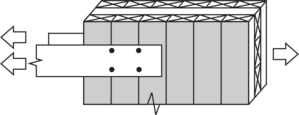
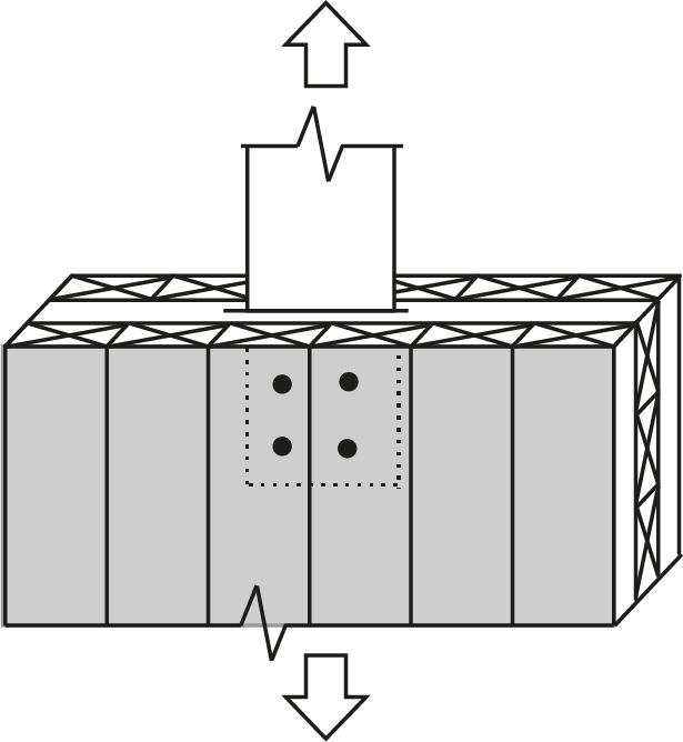
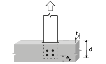
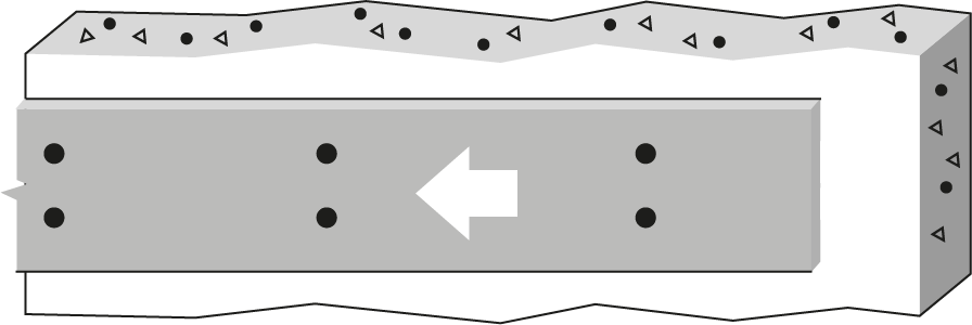
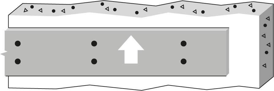
7/8″ Bolt or dowel Single Shear, D. Fir-L glulam to 6mm steel plates |
 |
|||||||||||||
| Wood Member | Fastener |
 |
|||||||||||||
|
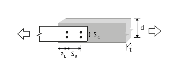
Thickness (mm) |
Depth (mm) |
No. of rows |
 |
No. of fasteners in a row | |||||||||||
| 2 | 3 | ||||||||||||||
| Bolt spacing in a row taken as the minimum of the loaded end distance3, aL, and the spacing between bolts in a row, SR (mm) | |||||||||||||||
| 89 | 133 | 178 | 222 | 267 | 89 | 133 | 178 | 222 | 267 | ||||||
| 80 | 114 | 1 | 0 | 15.5(R) | 23.3(R) | 31.1(R) | 38.8(R) | 46.6(R) | 23.3(R) | 34.9(R) | 46.6(R) | 58.2(R) | 69.9(R) | ||
| 80 | 228 | 2 | 66.675 | 31.1(R) | 46.6(R) | 62.1(R) | 77.7(R) | 93.2(R) | 46.6(R) | 69.9(R) | 93.2(R) | 107(G) | 118(G) | ||
| 80 | 228 | 2 | 111.125 | 31.1(R) | 46.6(R) | 62.1(R) | 77.7(R) | 93.2(R) | 46.6(R) | 69.9(R) | 93.2(R) | 116(R) | 140(R) | ||
| 80 | 266 | 2 | 125 | 31.1(R) | 46.6(R) | 62.1(R) | 77.7(R) | 93.2(R) | 46.6(R) | 69.9(R) | 93.2(R) | 116(R) | 140(R) | ||
| 130 | 152 | 1 | 0 | 25.2(R) | 37.9(R) | 49.2(g) | 49.2(g) | 49.2(g) | 37.9(R) | 56.8(R) | 73.8(g) | 73.8(g) | 73.8(g) | ||
| 130 | 228 | 2 | 66.675 | 50.5(R) | 75.7(R) | 98.4(g) | 98.4(g) | 98.4(g) | 75.7(R) | 114(R) | 148(g) | 148(g) | 148(g) | ||
| 130 | 228 | 2 | 111.125 | 50.5(R) | 75.7(R) | 98.4(g) | 98.4(g) | 98.4(g) | 75.7(R) | 114(R) | 148(g) | 148(g) | 148(g) | ||
| 130 | 266 | 2 | 125 | 50.5(R) | 75.7(R) | 98.4(g) | 98.4(g) | 98.4(g) | 75.7(R) | 114(R) | 148(g) | 148(g) | 148(g) | ||
| 175 | 190 | 1 | 0 | 34.0(R) | 49.2(g) | 49.2(g) | 49.2(g) | 49.2(g) | 51.0(R) | 73.8(g) | 73.8(g) | 73.8(g) | 73.8(g) | ||
| 175 | 228 | 2 | 66.675 | 68.0(R) | 98.4(g) | 98.4(g) | 98.4(g) | 98.4(g) | 102(R) | 148(g) | 148(g) | 148(g) | 148(g) | ||
| 175 | 228 | 2 | 111.125 | 68.0(R) | 98.4(g) | 98.4(g) | 98.4(g) | 98.4(g) | 102(R) | 148(g) | 148(g) | 148(g) | 148(g) | ||
| 175 | 266 | 2 | 125 | 68.0(R) | 98.4(g) | 98.4(g) | 98.4(g) | 98.4(g) | 102(R) | 148(g) | 148(g) | 148(g) | 148(g) | ||
| 215 | 266 | 1 | 0 | 41.7(R) | 49.2(g) | 49.2(g) | 49.2(g) | 49.2(g) | 62.6(R) | 73.8(g) | 73.8(g) | 73.8(g) | 73.8(g) | ||
| 215 | 266 | 2 | 66.675 | 83.5(R) | 98.4(g) | 98.4(g) | 98.4(g) | 98.4(g) | 125(R) | 148(g) | 148(g) | 148(g) | 148(g) | ||
| 215 | 266 | 2 | 111.125 | 83.5(R) | 98.4(g) | 98.4(g) | 98.4(g) | 98.4(g) | 125(R) | 148(g) | 148(g) | 148(g) | 148(g) | ||
| 215 | 266 | 2 | 125 | 83.5(R) | 98.4(g) | 98.4(g) | 98.4(g) | 98.4(g) | 125(R) | 148(g) | 148(g) | 148(g) | 148(g) | ||
| 265 | 342 | 1 | 0 | 49.2(g) | 49.2(g) | 49.2(g) | 49.2(g) | 49.2(g) | 73.8(g) | 73.8(g) | 73.8(g) | 73.8(g) | 73.8(g) | ||
| 265 | 342 | 2 | 66.675 | 98.4(g) | 98.4(g) | 98.4(g) | 98.4(g) | 98.4(g) | 148(g) | 148(g) | 148(g) | 148(g) | 148(g) | ||
| 265 | 342 | 2 | 111.125 | 98.4(g) | 98.4(g) | 98.4(g) | 98.4(g) | 98.4(g) | 148(g) | 148(g) | 148(g) | 148(g) | 148(g) | ||
| 265 | 342 | 2 | 125 | 98.4(g) | 98.4(g) | 98.4(g) | 98.4(g) | 98.4(g) | 148(g) | 148(g) | 148(g) | 148(g) | 148(g) | ||
| 315 | 380 | 1 | 0 | 49.2(g) | 49.2(g) | 49.2(g) | 49.2(g) | 49.2(g) | 73.8(g) | 73.8(g) | 73.8(g) | 73.8(g) | 73.8(g) | ||
| 315 | 380 | 2 | 66.675 | 98.4(g) | 98.4(g) | 98.4(g) | 98.4(g) | 98.4(g) | 148(g) | 148(g) | 148(g) | 148(g) | 148(g) | ||
| 315 | 380 | 2 | 111.125 | 98.4(g) | 98.4(g) | 98.4(g) | 98.4(g) | 98.4(g) | 148(g) | 148(g) | 148(g) | 148(g) | 148(g) | ||
| 315 | 380 | 2 | 125 | 98.4(g) | 98.4(g) | 98.4(g) | 98.4(g) | 98.4(g) | 148(g) | 148(g) | 148(g) | 148(g) | 148(g) | ||
|
Notes:
|
. | ||||||||||||||