


 |
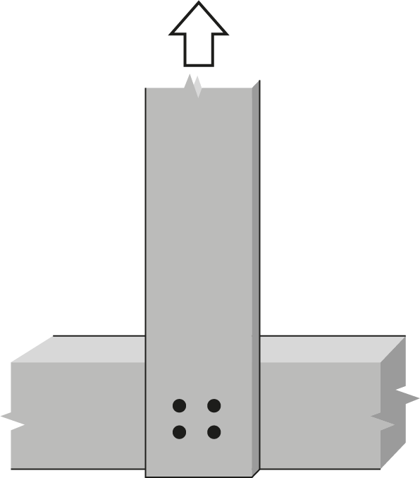
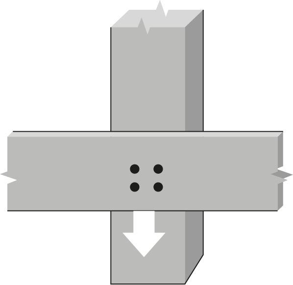
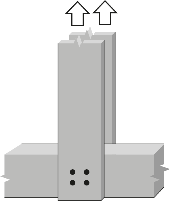
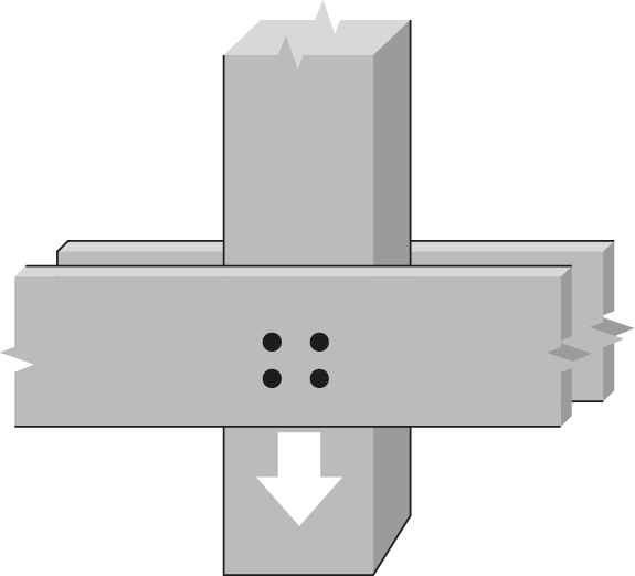
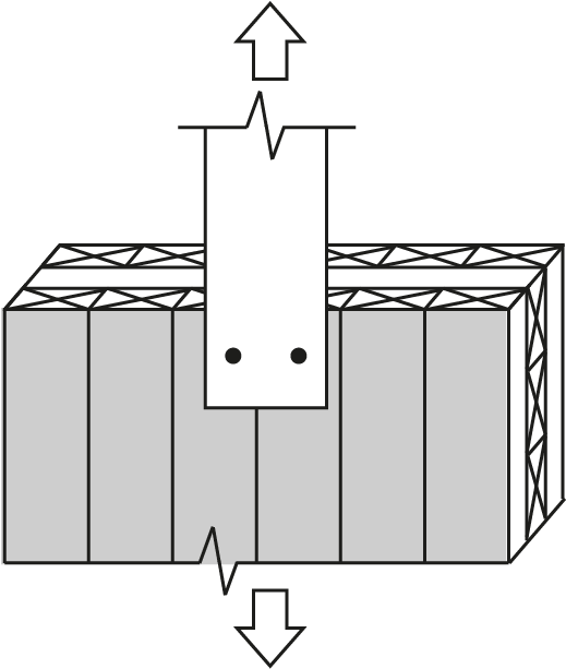
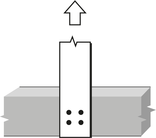
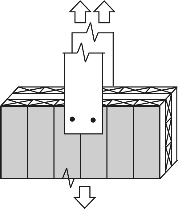
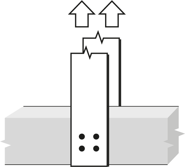
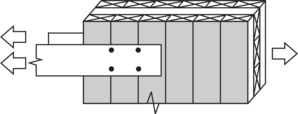
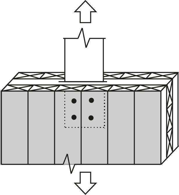
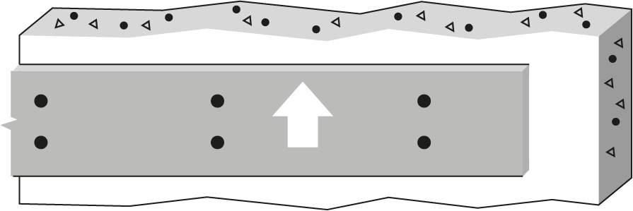
5/8″ Bolt or dowel Single Shear, D. Fir-L glulam to 6mm steel plates |
 |
|||||||||||||
| Wood Member | Fastener |
 |
|||||||||||||
|
Thickness (mm) |
Depth (mm) |
No. of rows |
 |
No. of fasteners in a row | |||||||||||
| 2 | 3 | ||||||||||||||
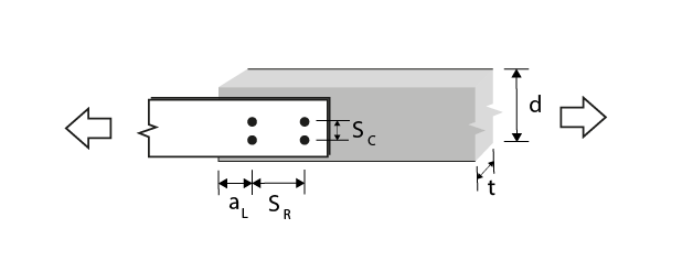
| Bolt spacing in a row taken as the minimum of the loaded end distance3, aL, and the spacing between bolts in a row, SR (mm) | |||||||||||||||
| 64 | 95 | 127 | 159 | 190 | 64 | 95 | 127 | 159 | 190 | ||||||
| 80 | 114 | 1 | 0 | 11.1(R) | 16.6(R) | 22.2(R) | 26.1(g) | 26.1(g) | 16.6(R) | 25.0(R) | 33.3(R) | 39.1(g) | 39.1(g) | ||
| 80 | 152 | 2 | 47.625 | 22.2(R) | 33.3(R) | 44.4(R) | 52.2(g) | 52.2(g) | 33.3(R) | 49.9(R) | 66.6(R) | 75.6(G) | 78.3(g) | ||
| 80 | 190 | 2 | 79.375 | 22.2(R) | 33.3(R) | 44.4(R) | 52.2(g) | 52.2(g) | 33.3(R) | 49.9(R) | 66.6(R) | 78.3(g) | 78.3(g) | ||
| 80 | 228 | 2 | 111.125 | 22.2(R) | 33.3(R) | 44.4(R) | 52.2(g) | 52.2(g) | 33.3(R) | 49.9(R) | 66.6(R) | 78.3(g) | 78.3(g) | ||
| 80 | 228 | 3 | 47.625 | 33.3(R) | 49.9(R) | 66.6(R) | 78.3(g) | 78.3(g) | 49.9(R) | 74.9(R) | 99.9(R) | 110(G) | 117(g) | ||
| 80 | 228 | 3 | 62.5 | 33.3(R) | 49.9(R) | 66.6(R) | 78.3(g) | 78.3(g) | 49.9(R) | 74.9(R) | 99.9(R) | 117(g) | 117(g) | ||
| 130 | 152 | 1 | 0 | 18.0(R) | 26.1(g) | 26.1(g) | 26.1(g) | 26.1(g) | 27.0(R) | 39.1(g) | 39.1(g) | 39.1(g) | 39.1(g) | ||
| 130 | 152 | 2 | 47.625 | 36.1(R) | 52.2(g) | 52.2(g) | 52.2(g) | 52.2(g) | 54.1(R) | 78.3(g) | 78.3(g) | 78.3(g) | 78.3(g) | ||
| 130 | 190 | 2 | 79.375 | 36.1(R) | 52.2(g) | 52.2(g) | 52.2(g) | 52.2(g) | 54.1(R) | 78.3(g) | 78.3(g) | 78.3(g) | 78.3(g) | ||
| 130 | 228 | 2 | 111.125 | 36.1(R) | 52.2(g) | 52.2(g) | 52.2(g) | 52.2(g) | 54.1(R) | 78.3(g) | 78.3(g) | 78.3(g) | 78.3(g) | ||
| 130 | 228 | 3 | 47.625 | 54.1(R) | 78.3(g) | 78.3(g) | 78.3(g) | 78.3(g) | 81.1(R) | 117(g) | 117(g) | 117(g) | 117(g) | ||
| 130 | 228 | 3 | 62.5 | 54.1(R) | 78.3(g) | 78.3(g) | 78.3(g) | 78.3(g) | 81.1(R) | 117(g) | 117(g) | 117(g) | 117(g) | ||
| 175 | 190 | 1 | 0 | 24.3(R) | 26.1(g) | 26.1(g) | 26.1(g) | 26.1(g) | 36.4(R) | 39.1(g) | 39.1(g) | 39.1(g) | 39.1(g) | ||
| 175 | 190 | 2 | 47.625 | 48.5(R) | 52.2(g) | 52.2(g) | 52.2(g) | 52.2(g) | 72.8(R) | 78.3(g) | 78.3(g) | 78.3(g) | 78.3(g) | ||
| 175 | 190 | 2 | 79.375 | 48.5(R) | 52.2(g) | 52.2(g) | 52.2(g) | 52.2(g) | 72.8(R) | 78.3(g) | 78.3(g) | 78.3(g) | 78.3(g) | ||
| 175 | 228 | 2 | 111.125 | 48.5(R) | 52.2(g) | 52.2(g) | 52.2(g) | 52.2(g) | 72.8(R) | 78.3(g) | 78.3(g) | 78.3(g) | 78.3(g) | ||
| 175 | 228 | 3 | 47.625 | 72.8(R) | 78.3(g) | 78.3(g) | 78.3(g) | 78.3(g) | 109(R) | 117(g) | 117(g) | 117(g) | 117(g) | ||
| 175 | 228 | 3 | 62.5 | 72.8(R) | 78.3(g) | 78.3(g) | 78.3(g) | 78.3(g) | 109(R) | 117(g) | 117(g) | 117(g) | 117(g) | ||
| 215 | 266 | 1 | 0 | 26.1(g) | 26.1(g) | 26.1(g) | 26.1(g) | 26.1(g) | 39.1(g) | 39.1(g) | 39.1(g) | 39.1(g) | 39.1(g) | ||
| 215 | 266 | 2 | 47.625 | 52.2(g) | 52.2(g) | 52.2(g) | 52.2(g) | 52.2(g) | 78.3(g) | 78.3(g) | 78.3(g) | 78.3(g) | 78.3(g) | ||
| 215 | 266 | 2 | 79.375 | 52.2(g) | 52.2(g) | 52.2(g) | 52.2(g) | 52.2(g) | 78.3(g) | 78.3(g) | 78.3(g) | 78.3(g) | 78.3(g) | ||
| 215 | 266 | 2 | 111.125 | 52.2(g) | 52.2(g) | 52.2(g) | 52.2(g) | 52.2(g) | 78.3(g) | 78.3(g) | 78.3(g) | 78.3(g) | 78.3(g) | ||
| 215 | 266 | 3 | 47.625 | 78.3(g) | 78.3(g) | 78.3(g) | 78.3(g) | 78.3(g) | 117(g) | 117(g) | 117(g) | 117(g) | 117(g) | ||
| 215 | 266 | 3 | 62.5 | 78.3(g) | 78.3(g) | 78.3(g) | 78.3(g) | 78.3(g) | 117(g) | 117(g) | 117(g) | 117(g) | 117(g) | ||
| 265 | 342 | 1 | 0 | 26.1(g) | 26.1(g) | 26.1(g) | 26.1(g) | 26.1(g) | 39.1(g) | 39.1(g) | 39.1(g) | 39.1(g) | 39.1(g) | ||
| 265 | 342 | 2 | 47.625 | 52.2(g) | 52.2(g) | 52.2(g) | 52.2(g) | 52.2(g) | 78.3(g) | 78.3(g) | 78.3(g) | 78.3(g) | 78.3(g) | ||
| 265 | 342 | 2 | 79.375 | 52.2(g) | 52.2(g) | 52.2(g) | 52.2(g) | 52.2(g) | 78.3(g) | 78.3(g) | 78.3(g) | 78.3(g) | 78.3(g) | ||
| 265 | 342 | 2 | 111.125 | 52.2(g) | 52.2(g) | 52.2(g) | 52.2(g) | 52.2(g) | 78.3(g) | 78.3(g) | 78.3(g) | 78.3(g) | 78.3(g) | ||
| 265 | 342 | 3 | 47.625 | 78.3(g) | 78.3(g) | 78.3(g) | 78.3(g) | 78.3(g) | 117(g) | 117(g) | 117(g) | 117(g) | 117(g) | ||
| 265 | 342 | 3 | 62.5 | 78.3(g) | 78.3(g) | 78.3(g) | 78.3(g) | 78.3(g) | 117(g) | 117(g) | 117(g) | 117(g) | 117(g) | ||
| 315 | 380 | 1 | 0 | 26.1(g) | 26.1(g) | 26.1(g) | 26.1(g) | 26.1(g) | 39.1(g) | 39.1(g) | 39.1(g) | 39.1(g) | 39.1(g) | ||
| 315 | 380 | 2 | 47.625 | 52.2(g) | 52.2(g) | 52.2(g) | 52.2(g) | 52.2(g) | 78.3(g) | 78.3(g) | 78.3(g) | 78.3(g) | 78.3(g) | ||
| 315 | 380 | 2 | 79.375 | 52.2(g) | 52.2(g) | 52.2(g) | 52.2(g) | 52.2(g) | 78.3(g) | 78.3(g) | 78.3(g) | 78.3(g) | 78.3(g) | ||
| 315 | 380 | 2 | 111.125 | 52.2(g) | 52.2(g) | 52.2(g) | 52.2(g) | 52.2(g) | 78.3(g) | 78.3(g) | 78.3(g) | 78.3(g) | 78.3(g) | ||
| 315 | 380 | 3 | 47.625 | 78.3(g) | 78.3(g) | 78.3(g) | 78.3(g) | 78.3(g) | 117(g) | 117(g) | 117(g) | 117(g) | 117(g) | ||
| 315 | 380 | 3 | 62.5 | 78.3(g) | 78.3(g) | 78.3(g) | 78.3(g) | 78.3(g) | 117(g) | 117(g) | 117(g) | 117(g) | 117(g) | ||
|
Notes:
|
. | ||||||||||||||