


 |
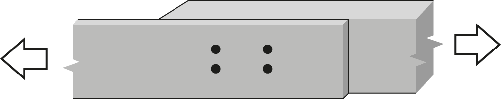
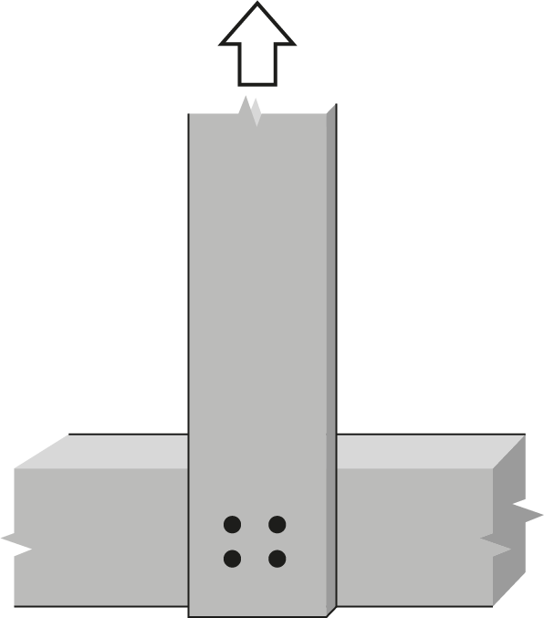
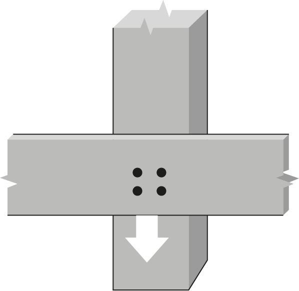
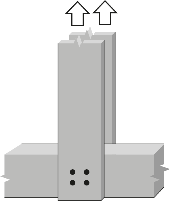
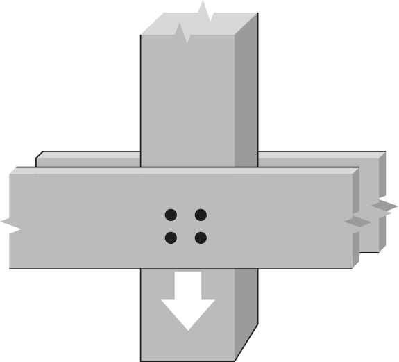
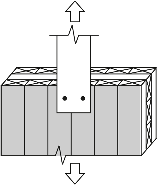
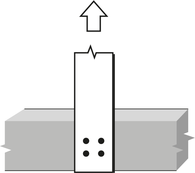
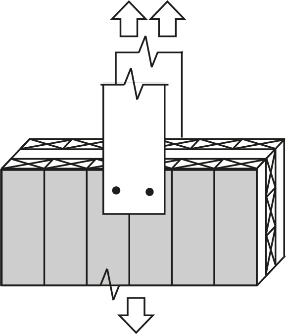
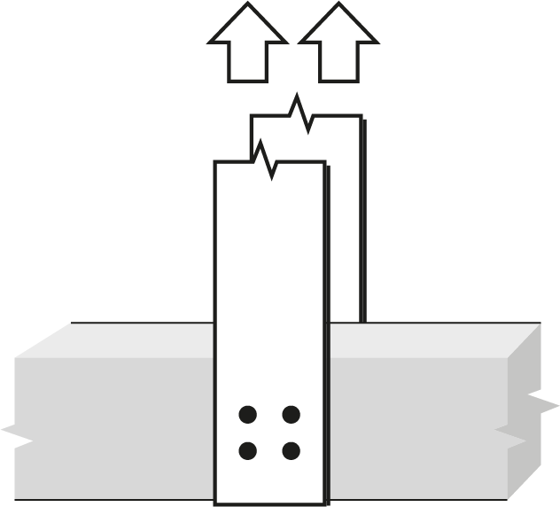
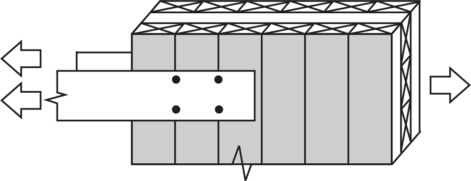
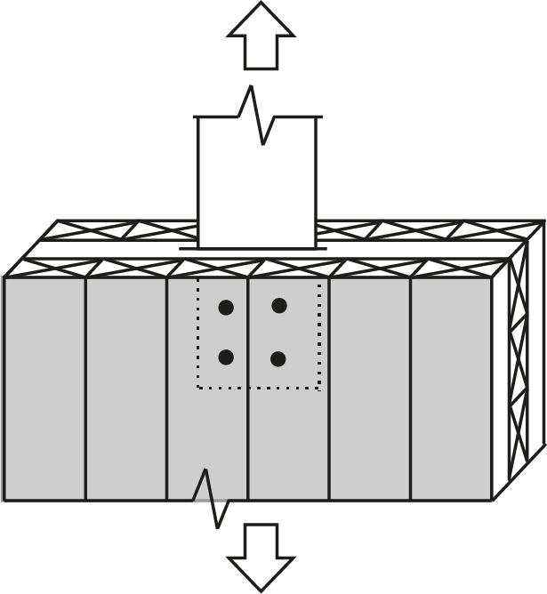
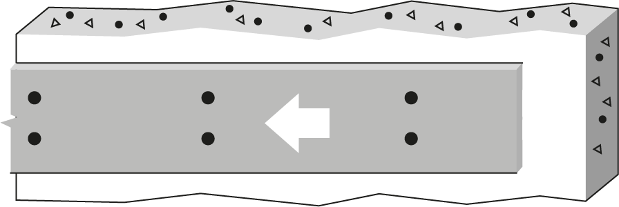
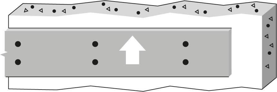
1″ Bolt or dowel Double Shear, S-P-F lumber |
 |
||||||||||||||||||
| Wood Member | Fastener |
 |
||||||||||||||||||
|
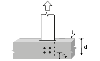
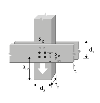
Thickness (mm) |
Main member depth (mm) d₂ |
No. of rows |
 |
 |
||||||||||||||||
| 140 | 140 | 140 | 140 | 140 | 286 | |||||||||||||||
 |
||||||||||||||||||||
| 1 | 2 | 3 | ||||||||||||||||||
 |
||||||||||||||||||||
|
Side, t₁ |
Main,
t₂ |
127 | 152 | 203 | 254 | 305 | 102 | 152 | 203 | 254 | 305 | 102 | 152 | 203 | 254 | 305 | ||||
| 38 | 38 | 140 | 1 | 0 | 6.08(R) | 7.30(R) | 9.73(R) | 10.6(a) 9.76 | 10.6(a) 9.76 | 9.73(R) | ||||||||||
| 38 | 38 | 235 | 2 | 76 | 12.2(R) 9.76 | 14.4(S) 9.76 | 14.4(S) 9.76 | 14.4(S) 9.76 | 14.4(S) 9.76 | 16.9(G) | ||||||||||
| 38 | 38 | 286 | 2 | 127 | 12.2(R) 9.76 | 14.4(S) 9.76 | 14.4(S) 9.76 | 14.4(S) 9.76 | 14.4(S) 9.76 | 19.5(R) 17.0 | ||||||||||
| 38 | 89 | 140 | 1 | 0 | 10.6(a) 9.76 | 10.6(a) 9.76 | 10.6(a) 9.76 | 10.6(a) 9.76 | 10.6(a) 9.76 | 21.3(a) 17.0 | ||||||||||
| 38 | 89 | 235 | 2 | 76 | 14.4(S) 9.76 | 14.4(S) 9.76 | 14.4(S) 9.76 | 14.4(S) 9.76 | 14.4(S) 9.76 | 32.1(S) 17.0 | ||||||||||
| 38 | 89 | 286 | 2 | 127 | 14.4(S) 9.76 | 14.4(S) 9.76 | 14.4(S) 9.76 | 14.4(S) 9.76 | 14.4(S) 9.76 | 32.1(S) 17.0 | ||||||||||
| 38 | 140 | 140 | 1 | 0 | 10.6(a) 9.76 | 10.6(a) 9.76 | 10.6(a) 9.76 | 10.6(a) 9.76 | 10.6(a) 9.76 | 21.3(a) 17.0 | ||||||||||
| 38 | 140 | 241 | 2 | 76 | 14.4(S) 9.76 | 14.4(S) 9.76 | 14.4(S) 9.76 | 14.4(S) 9.76 | 14.4(S) 9.76 | 32.1(S) 17.0 | ||||||||||
| 38 | 140 | 292 | 2 | 127 | 14.4(S) 9.76 | 14.4(S) 9.76 | 14.4(S) 9.76 | 14.4(S) 9.76 | 14.4(S) 9.76 | 32.1(S) 17.0 | ||||||||||
| 89 | 89 | 140 | 1 | 0 | 14.2(R) | 17.1(R) | 21.2(d) | 21.2(d) | 21.2(d) | 22.8(R) | ||||||||||
| 89 | 89 | 235 | 2 | 76 | 28.5(R) 24.5 | 33.8(S) 24.5 | 33.8(S) 24.5 | 33.8(S) 24.5 | 33.8(S) 24.5 | 39.5(G) | ||||||||||
| 89 | 89 | 286 | 2 | 127 | 28.5(R) 24.5 | 33.8(S) 24.5 | 33.8(S) 24.5 | 33.8(S) 24.5 | 33.8(S) 24.5 | 45.6(R) 43.7 | ||||||||||
| 89 | 140 | 140 | 1 | 0 | 17.9(R) | 21.2(d) | 21.2(d) | 21.2(d) | 21.2(d) | 28.7(R) | ||||||||||
| 89 | 140 | 241 | 2 | 76 | 28.9(G) 24.5 | 32.5(G) 24.5 | 33.8(S) 24.5 | 33.8(S) 24.5 | 33.8(S) 24.5 | 39.7(G) | ||||||||||
| 89 | 140 | 292 | 2 | 127 | 33.8(S) 24.5 | 33.8(S) 24.5 | 33.8(S) 24.5 | 33.8(S) 24.5 | 33.8(S) 24.5 | 51.1(G) 43.7 | ||||||||||
| 89 | 191 | 140 | 1 | 0 | 21.2(d) | 21.2(d) | 21.2(d) | 21.2(d) | 21.2(d) | 39.1(R) | ||||||||||
| 89 | 191 | 241 | 2 | 76 | 33.8(S) 24.5 | 33.8(S) 24.5 | 33.8(S) 24.5 | 33.8(S) 24.5 | 33.8(S) 24.5 | 56.1(G) 43.7 | ||||||||||
| 89 | 191 | 292 | 2 | 127 | 33.8(S) 24.5 | 33.8(S) 24.5 | 33.8(S) 24.5 | 33.8(S) 24.5 | 33.8(S) 24.5 | 69.7(G) 43.7 | ||||||||||
|
Notes:
|
... | |||||||||||||||||||