


 |
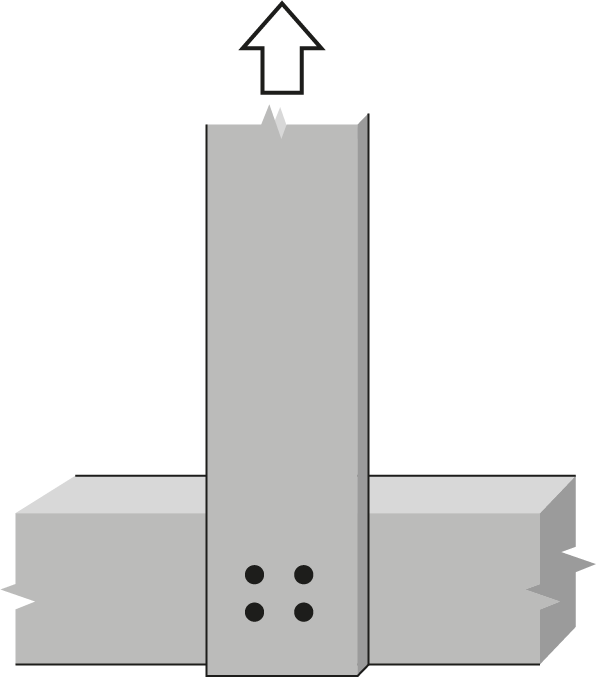
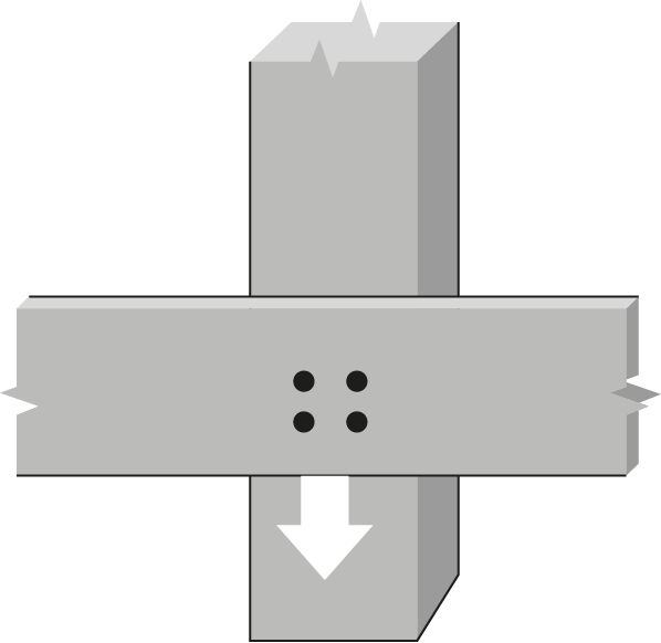
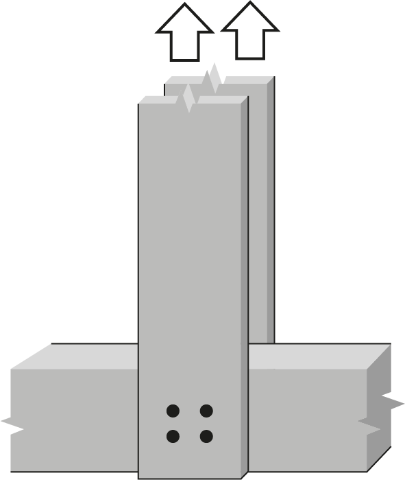
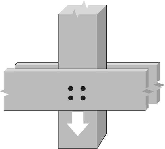
7/8″ Bolt or dowel Single Shear, Northern lumber |
 |
||||||||||||||||||
| Wood Member | Fastener |
 |
||||||||||||||||||
|
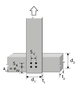
Thickness (mm) |
Side member depth (mm) d₁ |
No. of rows |
 |
 |
||||||||||||||||
| 235- 241 | 235- 241 | 286- 292 | 343 | 292 | ||||||||||||||||
 |
||||||||||||||||||||
| 111 | 133 | 178 | 222 | 267 | 111 | 133 | 178 | 222 | 267 | 111 | 133 | 178 | 222 | 267 | ||||||
 |
||||||||||||||||||||
| 1 | 2 | 3 | ||||||||||||||||||
 |
||||||||||||||||||||
|
Side, t₁ |
Main,
t₂ |
0 | 0 | 0 | 0 | 0 | 89 | 133 | 178 | 222 | 267 | 89 | 133 | 178 | 222 | 267 | ||||
| 38 | 38 | 140 | 1 | 0 | 2.65(f) | 2.65(f) | 2.65(f) | |||||||||||||
| 38 | 38 | 235 | 2 | 67 | 5.30(f) 4.04 | 4.98(S) 3.31 | 4.91(S) 3.21 | |||||||||||||
| 38 | 38 | 235 | 2 | 111 | 5.30(f) 4.04 | 4.98(S) 3.31 | 4.91(S) 3.21 | |||||||||||||
| 38 | 89 | 140 | 1 | 0 | 3.00(R) | 3.60(R) | 3.73(f) | |||||||||||||
| 38 | 89 | 235 | 2 | 67 | 5.99(R) | 7.19(R) | 7.47(f) | |||||||||||||
| 38 | 89 | 235 | 2 | 111 | 5.99(R) | 7.19(R) | 7.47(f) | |||||||||||||
| 38 | 140 | 140 | 1 | 0 | 3.00(R) | 3.60(R) | 4.80(R) | 4.82(f) | 4.80(R) | |||||||||||
| 38 | 140 | 235 | 2 | 67 | 5.99(R) | 7.19(R) | 9.31(G) | 9.64(f) | 9.31(G) | |||||||||||
| 38 | 140 | 235 | 2 | 111 | 5.99(R) | 7.19(R) | 9.59(R) | 9.64(f) | 9.59(R) | |||||||||||
| 89 | 89 | 140 | 1 | 0 | 6.20(f) | 6.20(f) | 6.20(f) | |||||||||||||
| 89 | 89 | 235 | 2 | 67 | 12.4(f) 10.3 | 11.7(S) 8.47 | 11.5(S) 8.26 | |||||||||||||
| 89 | 89 | 235 | 2 | 111 | 12.4(f) 10.3 | 11.7(S) 8.47 | 11.5(S) 8.26 | |||||||||||||
| 89 | 140 | 140 | 1 | 0 | 7.02(R) | 7.29(f) | 7.29(f) | 7.29(f) | 11.2(R) | |||||||||||
| 89 | 140 | 235 | 2 | 67 | 14.0(R) 13.1 | 14.6(f) 10.9 | 14.6(f) 10.6 | 14.6(f) 10.1 | 21.8(G) 16.7 | |||||||||||
| 89 | 140 | 235 | 2 | 111 | 14.0(R) 13.1 | 14.6(f) 10.9 | 14.6(f) 10.6 | 14.6(f) 10.1 | 22.5(R) 16.7 | |||||||||||
| 89 | 191 | 140 | 1 | 0 | 7.02(R) | 8.38(f) | 8.38(f) | 8.38(f) | 11.2(R) | |||||||||||
| 89 | 191 | 235 | 2 | 67 | 14.0(R) | 16.8(f) 14.8 | 16.8(f) 14.4 | 16.8(f) 13.8 | 21.8(G) | |||||||||||
| 89 | 191 | 235 | 2 | 111 | 14.0(R) | 16.8(f) 14.8 | 16.8(f) 14.4 | 16.8(f) 13.8 | 22.5(R) | |||||||||||
|
Notes:
|
||||||||||||||||||||