


 |
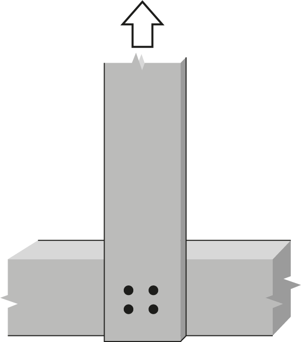
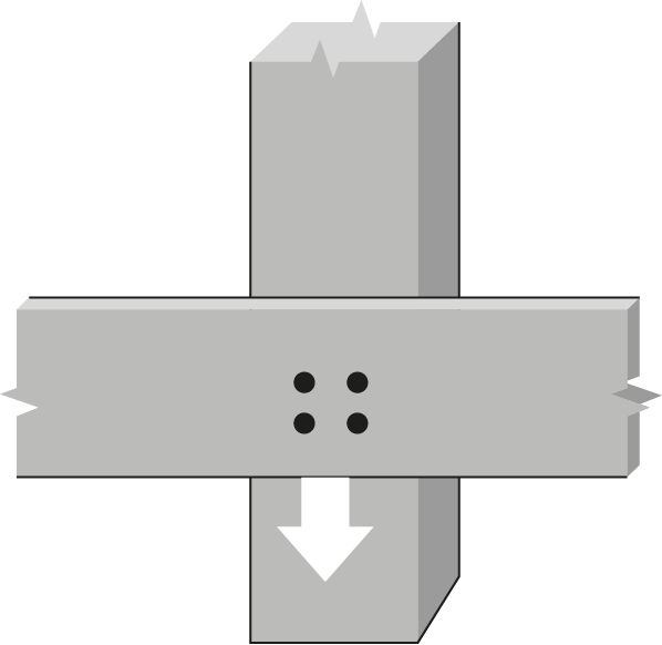
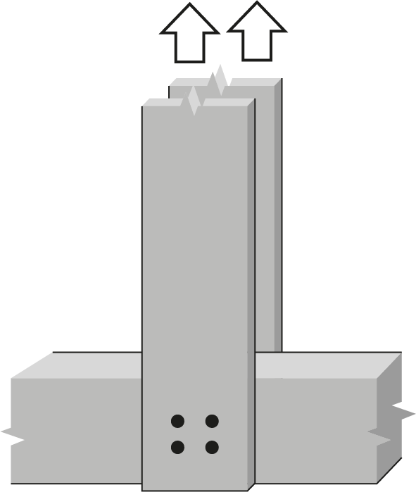
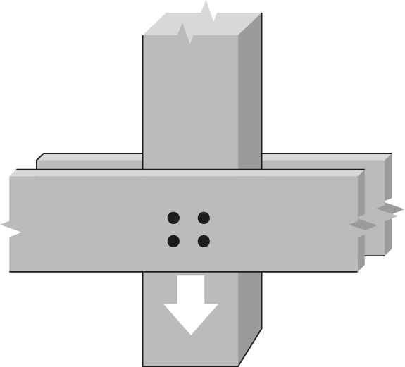
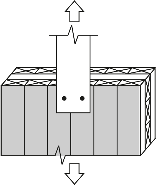
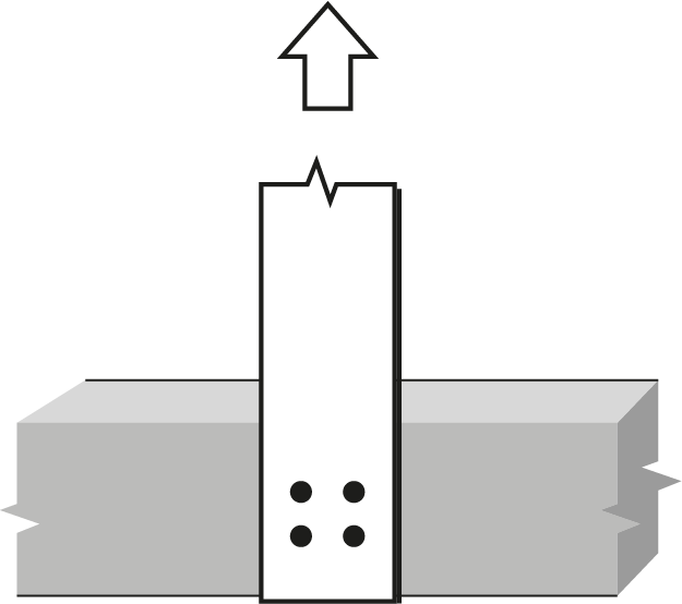
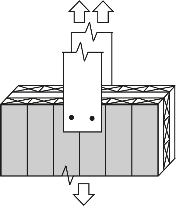
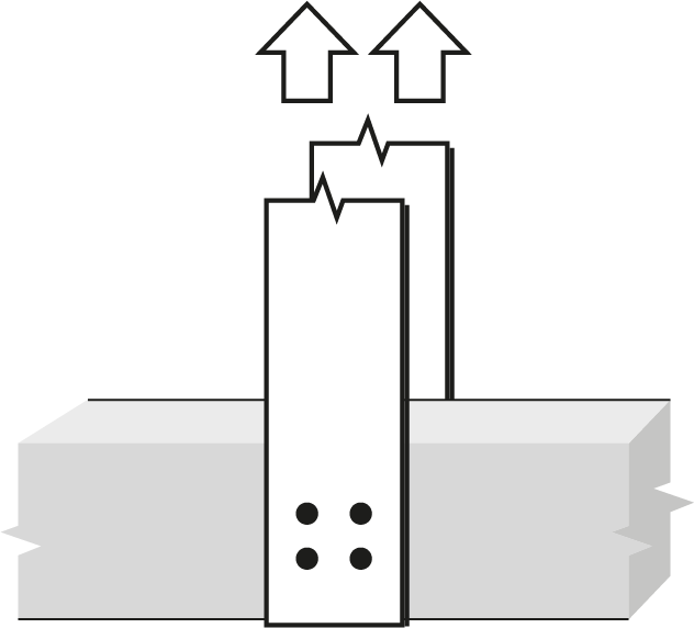
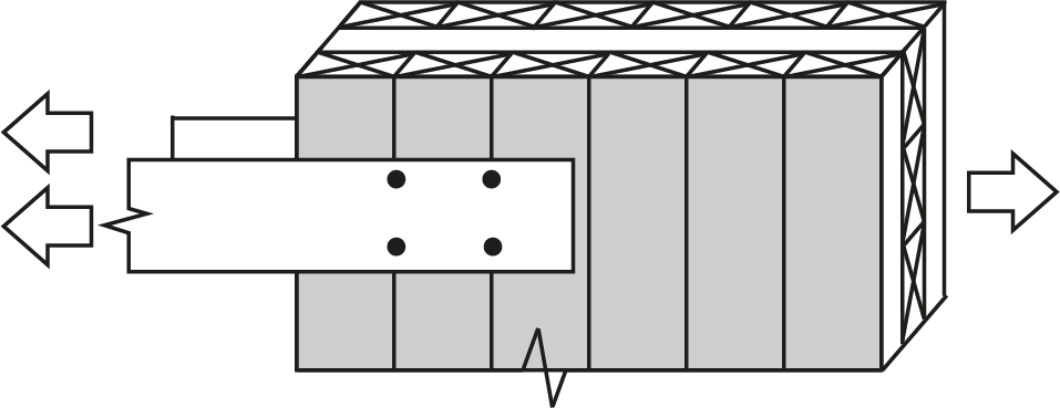
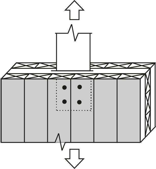
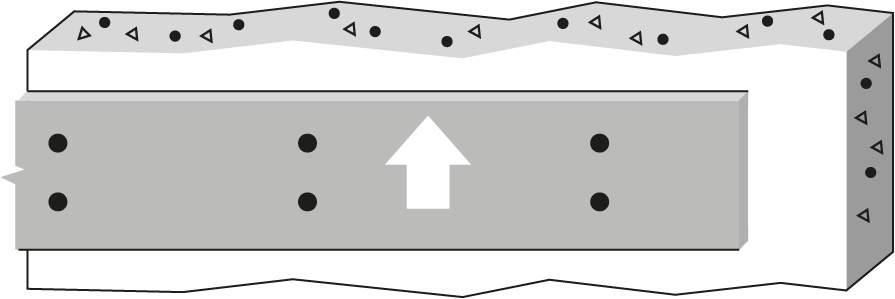
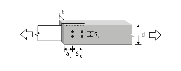
7/8″ Bolt or dowel Double Shear, 6 mm steel internal plates to Spruce-Pine glulam |
 |
|||||||||||||
| Wood Member | Fastener |
 |
|||||||||||||
|
Thickness (mm) |
Depth (mm) |
No. of rows |
 |
No. of fasteners in a row | |||||||||||
| 2 | 3 | ||||||||||||||
| Bolt spacing in a row taken as the minimum of the loaded end distance4, aL, and the spacing between bolts in a row, SR (mm) | |||||||||||||||
| 89 | 133 | 178 | 222 | 267 | 89 | 133 | 178 | 222 | 267 | ||||||
| 80 | 190 | 1 | 0 | 11.9(R) | 17.8(R) | 23.8(R) | 29.7(R) | 35.7(R) | 17.8(R) | 26.8(R) | 35.7(R) | 44.6(R) | 53.5(R) | ||
| 80 | 342 | 2 | 66.675 | 23.8(R) | 35.7(R) | 47.6(R) | 59.5(R) | 71.0(G) | 35.7(R) | 53.5(R) | 71.0(G) | 80.0(G) | 88.9(G) | ||
| 80 | 342 | 2 | 111.125 | 23.8(R) | 35.7(R) | 47.6(R) | 59.5(R) | 71.4(R) | 35.7(R) | 53.5(R) | 71.4(R) | 89.2(R) | 107(R) | ||
| 80 | 342 | 2 | 125 | 23.8(R) | 35.7(R) | 47.6(R) | 59.5(R) | 71.4(R) | 35.7(R) | 53.5(R) | 71.4(R) | 89.2(R) | 107(R) | ||
| 130 | 152 | 1 | 0 | 20.4(R) | 30.6(R) | 40.8(R) | 51.0(R) | 61.2(R) | 30.6(R) | 45.9(R) | 61.2(R) | 76.4(R) | 91.7(R) | ||
| 130 | 266 | 2 | 66.675 | 40.8(R) | 61.2(R) | 81.5(R) | 102(R) | 122(G) | 61.2(R) | 91.7(R) | 122(G) | 137(G) | 152(G) | ||
| 130 | 266 | 2 | 111.125 | 40.8(R) | 61.2(R) | 81.5(R) | 102(R) | 122(R) | 61.2(R) | 91.7(R) | 122(R) | 153(R) | 183(R) | ||
| 130 | 266 | 2 | 125 | 40.8(R) | 61.2(R) | 81.5(R) | 102(R) | 122(R) | 61.2(R) | 91.7(R) | 122(R) | 153(R) | 183(R) | ||
| 130 | 418 | 3 | 62.5 | 61.2(R) | 91.7(R) | 122(R) | 153(R) | 170(G) | 91.7(R) | 138(R) | 170(G) | 186(G) | 201(G) | ||
| 130 | 418 | 3 | 62.5 | 61.2(R) | 91.7(R) | 122(R) | 153(R) | 170(G) | 91.7(R) | 138(R) | 170(G) | 186(G) | 201(G) | ||
| 175 | 190 | 1 | 0 | 28.0(R) | 42.0(R) | 56.1(R) | 66.7(d) | 66.7(d) | 42.0(R) | 63.1(R) | 84.1(R) | 100(d) | 100(d) | ||
| 175 | 266 | 2 | 66.675 | 56.1(R) | 84.1(R) | 112(R) | 133(d) | 133(d) | 84.1(R) | 126(R) | 167(G) | 188(G) | 200(d) | ||
| 175 | 266 | 2 | 111.125 | 56.1(R) | 84.1(R) | 112(R) | 133(d) | 133(d) | 84.1(R) | 126(R) | 168(R) | 200(d) | 200(d) | ||
| 175 | 266 | 2 | 125 | 56.1(R) | 84.1(R) | 112(R) | 133(d) | 133(d) | 84.1(R) | 126(R) | 168(R) | 200(d) | 200(d) | ||
| 175 | 380 | 3 | 62.5 | 84.1(R) | 126(R) | 168(R) | 200(d) | 200(d) | 126(R) | 189(R) | 234(G) | 255(G) | 276(G) | ||
| 175 | 380 | 3 | 62.5 | 84.1(R) | 126(R) | 168(R) | 200(d) | 200(d) | 126(R) | 189(R) | 234(G) | 255(G) | 276(G) | ||
| 215 | 266 | 1 | 0 | 34.8(R) | 52.2(R) | 69.7(R) | 71.6(d) | 71.6(d) | 52.2(R) | 78.4(R) | 104(R) | 107(d) | 107(d) | ||
| 215 | 266 | 2 | 66.675 | 69.7(R) | 104(R) | 139(R) | 143(d) | 143(d) | 104(R) | 157(R) | 208(G) | 215(d) | 215(d) | ||
| 215 | 266 | 2 | 111.125 | 69.7(R) | 104(R) | 139(R) | 143(d) | 143(d) | 104(R) | 157(R) | 209(R) | 215(d) | 215(d) | ||
| 215 | 266 | 2 | 125 | 69.7(R) | 104(R) | 139(R) | 143(d) | 143(d) | 104(R) | 157(R) | 209(R) | 215(d) | 215(d) | ||
| 215 | 342 | 3 | 62.5 | 104(R) | 157(R) | 209(R) | 215(d) | 215(d) | 157(R) | 235(R) | 291(G) | 317(G) | 322(d) | ||
| 215 | 342 | 3 | 62.5 | 104(R) | 157(R) | 209(R) | 215(d) | 215(d) | 157(R) | 235(R) | 291(G) | 317(G) | 322(d) | ||
| 265 | 342 | 1 | 0 | 43.3(R) | 65.0(R) | 77.7(d) | 77.7(d) | 77.7(d) | 65.0(R) | 97.5(R) | 117(d) | 117(d) | 117(d) | ||
| 265 | 342 | 2 | 66.675 | 86.6(R) | 130(R) | 155(d) | 155(d) | 155(d) | 130(R) | 195(R) | 233(d) | 233(d) | 233(d) | ||
| 265 | 342 | 2 | 111.125 | 86.6(R) | 130(R) | 155(d) | 155(d) | 155(d) | 130(R) | 195(R) | 233(d) | 233(d) | 233(d) | ||
| 265 | 342 | 2 | 125 | 86.6(R) | 130(R) | 155(d) | 155(d) | 155(d) | 130(R) | 195(R) | 233(d) | 233(d) | 233(d) | ||
| 265 | 342 | 3 | 62.5 | 130(R) | 195(R) | 233(d) | 233(d) | 233(d) | 195(R) | 292(R) | 350(d) | 350(d) | 350(d) | ||
| 265 | 342 | 3 | 62.5 | 130(R) | 195(R) | 233(d) | 233(d) | 233(d) | 195(R) | 292(R) | 350(d) | 350(d) | 350(d) | ||
| 315 | 380 | 1 | 0 | 51.8(R) | 77.7(R) | 83.8(d) | 83.8(d) | 83.8(d) | 77.7(R) | 117(R) | 126(d) | 126(d) | 126(d) | ||
| 315 | 380 | 2 | 66.675 | 104(R) | 155(R) | 168(d) | 168(d) | 168(d) | 155(R) | 233(R) | 251(d) | 251(d) | 251(d) | ||
| 315 | 380 | 2 | 111.125 | 104(R) | 155(R) | 168(d) | 168(d) | 168(d) | 155(R) | 233(R) | 251(d) | 251(d) | 251(d) | ||
| 315 | 380 | 2 | 125 | 104(R) | 155(R) | 168(d) | 168(d) | 168(d) | 155(R) | 233(R) | 251(d) | 251(d) | 251(d) | ||
| 315 | 380 | 3 | 62.5 | 155(R) | 233(R) | 251(d) | 251(d) | 251(d) | 233(R) | 350(R) | 377(d) | 377(d) | 377(d) | ||
| 315 | 380 | 3 | 62.5 | 155(R) | 233(R) | 251(d) | 251(d) | 251(d) | 233(R) | 350(R) | 377(d) | 377(d) | 377(d) | ||
|
Notes:
|
|||||||||||||||