


 |
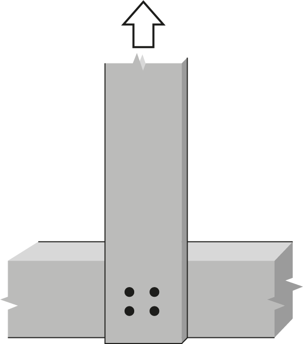
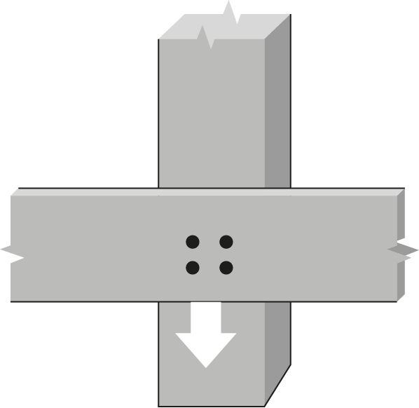
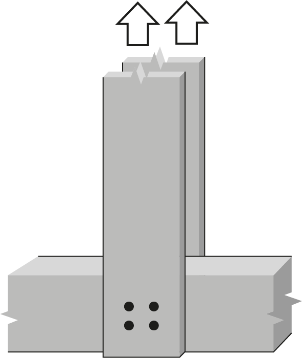
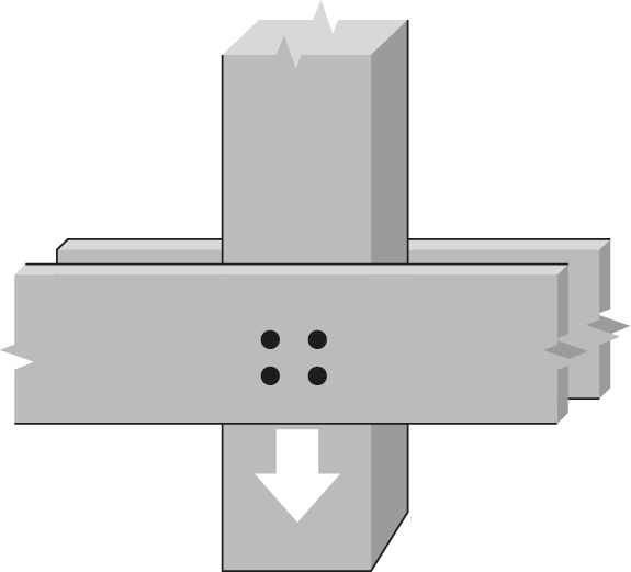
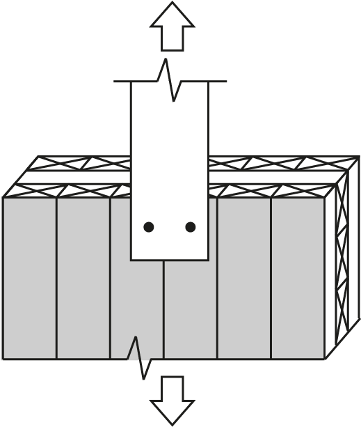
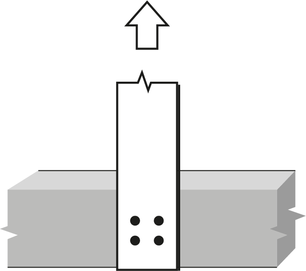
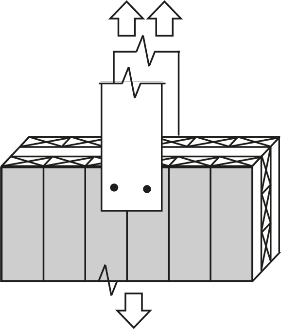
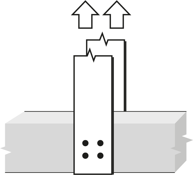
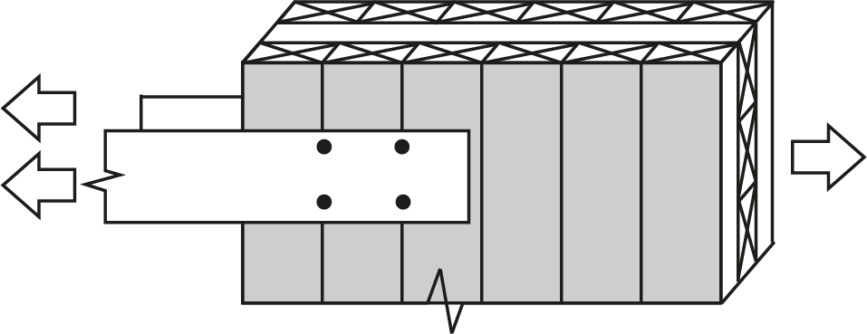
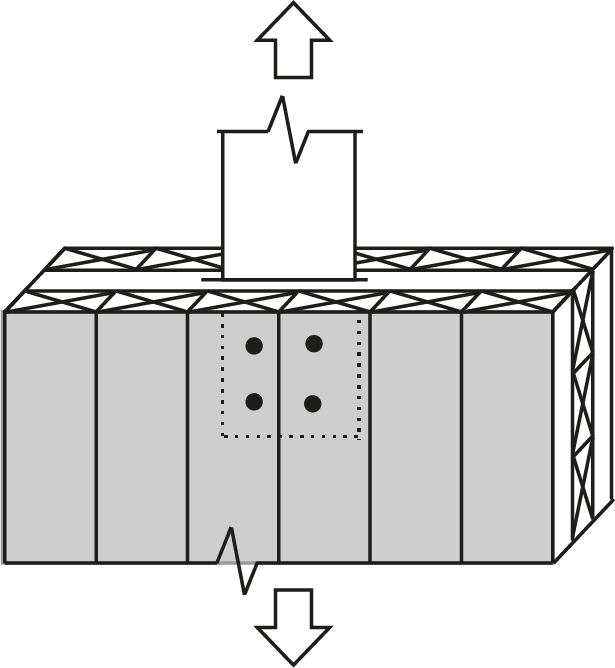
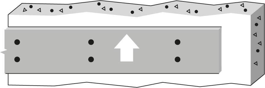
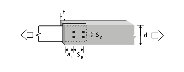
1″ Bolt or dowel Double Shear, 6mm steel internal plate to D. Fir-L glulam |
 |
|||||||||||||
| Wood Member | Fastener |
 |
|||||||||||||
|
Thickness (mm) |
Depth (mm) |
No. of rows |
 |
No. of fasteners in a row | |||||||||||
| 2 | 3 | ||||||||||||||
| Bolt spacing in a row taken as the minimum of the loaded end distance4, aL, and the spacing between bolts in a row, SR (mm) | |||||||||||||||
| 102 | 152 | 203 | 254 | 305 | 102 | 152 | 203 | 254 | 305 | ||||||
| 80 | 228 | 1 | 0 | 15.5(R) | 23.3(R) | 31.1(R) | 38.8(R) | 46.6(R) | 23.3(R) | 34.9(R) | 46.6(R) | 58.2(R) | 69.9(R) | ||
| 80 | 418 | 2 | 76.2 | 31.1(R) | 46.6(R) | 62.1(R) | 77.7(R) | 93.2(R) | 46.6(R) | 69.9(R) | 93.2(R) | 107(G) | 119(G) | ||
| 80 | 418 | 2 | 125 | 31.1(R) | 46.6(R) | 62.1(R) | 77.7(R) | 93.2(R) | 46.6(R) | 69.9(R) | 93.2(R) | 116(R) | 140(R) | ||
| 80 | 418 | 2 | 125 | 31.1(R) | 46.6(R) | 62.1(R) | 77.7(R) | 93.2(R) | 46.6(R) | 69.9(R) | 93.2(R) | 116(R) | 140(R) | ||
| 130 | 152 | 1 | 0 | 26.6(R) | 39.9(R) | 53.3(R) | 66.6(R) | 79.9(R) | 39.9(R) | 59.9(R) | 79.9(R) | 99.9(R) | 120(R) | ||
| 130 | 304 | 2 | 76.2 | 53.3(R) | 79.9(R) | 107(R) | 133(R) | 160(R) | 79.9(R) | 120(R) | 160(R) | 183(G) | 203(G) | ||
| 130 | 304 | 2 | 125 | 53.3(R) | 79.9(R) | 107(R) | 133(R) | 160(R) | 79.9(R) | 120(R) | 160(R) | 200(R) | 240(R) | ||
| 130 | 304 | 2 | 125 | 53.3(R) | 79.9(R) | 107(R) | 133(R) | 160(R) | 79.9(R) | 120(R) | 160(R) | 200(R) | 240(R) | ||
| 130 | 456 | 3 | 62.5 | 79.9(R) | 120(R) | 160(R) | 187(G) | 200(G) | 120(R) | 180(R) | 200(G) | 220(G) | 240(G) | ||
| 130 | 456 | 3 | 62.5 | 79.9(R) | 120(R) | 160(R) | 187(G) | 200(G) | 120(R) | 180(R) | 200(G) | 220(G) | 240(G) | ||
| 175 | 190 | 1 | 0 | 36.6(R) | 54.9(R) | 73.2(R) | 87.5(d) | 87.5(d) | 54.9(R) | 82.4(R) | 110(R) | 131(d) | 131(d) | ||
| 175 | 304 | 2 | 76.2 | 73.2(R) | 110(R) | 146(R) | 175(d) | 175(d) | 110(R) | 165(R) | 220(R) | 252(G) | 262(d) | ||
| 175 | 304 | 2 | 125 | 73.2(R) | 110(R) | 146(R) | 175(d) | 175(d) | 110(R) | 165(R) | 220(R) | 262(d) | 262(d) | ||
| 175 | 304 | 2 | 125 | 73.2(R) | 110(R) | 146(R) | 175(d) | 175(d) | 110(R) | 165(R) | 220(R) | 262(d) | 262(d) | ||
| 175 | 418 | 3 | 62.5 | 110(R) | 165(R) | 220(R) | 257(G) | 262(d) | 165(R) | 247(R) | 275(G) | 303(G) | 330(G) | ||
| 175 | 418 | 3 | 62.5 | 110(R) | 165(R) | 220(R) | 257(G) | 262(d) | 165(R) | 247(R) | 275(G) | 303(G) | 330(G) | ||
| 215 | 266 | 1 | 0 | 45.5(R) | 68.2(R) | 91.0(R) | 93.4(d) | 93.4(d) | 68.2(R) | 102(R) | 136(R) | 140(d) | 140(d) | ||
| 215 | 266 | 2 | 76.2 | 91.0(R) | 136(R) | 182(R) | 187(d) | 187(d) | 136(R) | 205(R) | 273(R) | 280(d) | 280(d) | ||
| 215 | 266 | 2 | 125 | 91.0(R) | 136(R) | 182(R) | 187(d) | 187(d) | 136(R) | 205(R) | 273(R) | 280(d) | 280(d) | ||
| 215 | 266 | 2 | 125 | 91.0(R) | 136(R) | 182(R) | 187(d) | 187(d) | 136(R) | 205(R) | 273(R) | 280(d) | 280(d) | ||
| 215 | 418 | 3 | 62.5 | 136(R) | 205(R) | 273(R) | 280(d) | 280(d) | 205(R) | 307(R) | 342(G) | 376(G) | 410(G) | ||
| 215 | 418 | 3 | 62.5 | 136(R) | 205(R) | 273(R) | 280(d) | 280(d) | 205(R) | 307(R) | 342(G) | 376(G) | 410(G) | ||
| 265 | 342 | 1 | 0 | 56.6(R) | 84.9(R) | 101(d) | 101(d) | 101(d) | 84.9(R) | 127(R) | 151(d) | 151(d) | 151(d) | ||
| 265 | 342 | 2 | 76.2 | 113(R) | 170(R) | 202(d) | 202(d) | 202(d) | 170(R) | 255(R) | 303(d) | 303(d) | 303(d) | ||
| 265 | 342 | 2 | 125 | 113(R) | 170(R) | 202(d) | 202(d) | 202(d) | 170(R) | 255(R) | 303(d) | 303(d) | 303(d) | ||
| 265 | 342 | 2 | 125 | 113(R) | 170(R) | 202(d) | 202(d) | 202(d) | 170(R) | 255(R) | 303(d) | 303(d) | 303(d) | ||
| 265 | 380 | 3 | 62.5 | 170(R) | 255(R) | 303(d) | 303(d) | 303(d) | 255(R) | 382(R) | 425(G) | 454(d) | 454(d) | ||
| 265 | 380 | 3 | 62.5 | 170(R) | 255(R) | 303(d) | 303(d) | 303(d) | 255(R) | 382(R) | 425(G) | 454(d) | 454(d) | ||
| 315 | 380 | 1 | 0 | 67.7(R) | 102(R) | 108(d) | 108(d) | 108(d) | 102(R) | 152(R) | 162(d) | 162(d) | 162(d) | ||
| 315 | 380 | 2 | 76.2 | 135(R) | 203(R) | 217(d) | 217(d) | 217(d) | 203(R) | 305(R) | 325(d) | 325(d) | 325(d) | ||
| 315 | 380 | 2 | 125 | 135(R) | 203(R) | 217(d) | 217(d) | 217(d) | 203(R) | 305(R) | 325(d) | 325(d) | 325(d) | ||
| 315 | 380 | 2 | 125 | 135(R) | 203(R) | 217(d) | 217(d) | 217(d) | 203(R) | 305(R) | 325(d) | 325(d) | 325(d) | ||
| 315 | 380 | 3 | 62.5 | 203(R) | 305(R) | 325(d) | 325(d) | 325(d) | 305(R) | 457(R) | 487(d) | 487(d) | 487(d) | ||
| 315 | 380 | 3 | 62.5 | 203(R) | 305(R) | 325(d) | 325(d) | 325(d) | 305(R) | 457(R) | 487(d) | 487(d) | 487(d) | ||
|
Notes:
|
|||||||||||||||