


 |
6 mm Steel plate to glulam | ||||||
|
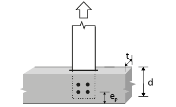
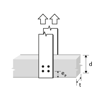
Wood member thickness t (mm) |
Bolt or dowel diameter (in) |
 |
|||||
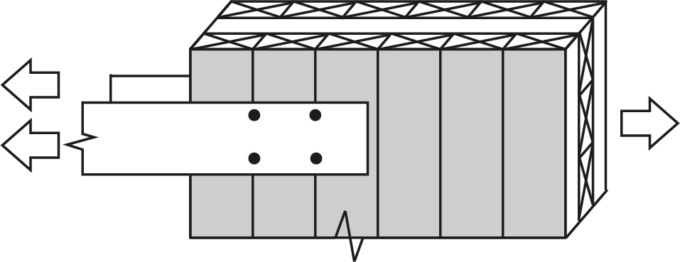
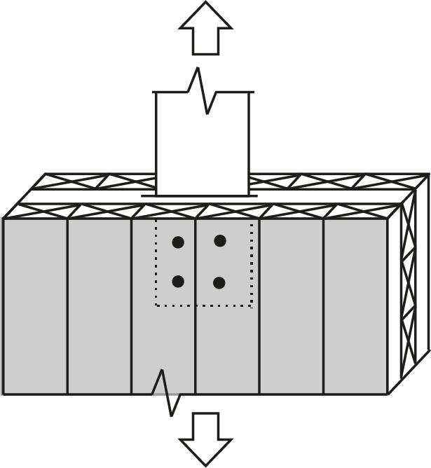
| Type 10 (double shear) | |||||||
 |
|||||||
| Glulam species | |||||||
| D.Fir-L | Spruce-Pine | ||||||
| 80 | 1/2 | 7.65(c) | 6.87(c) | ||||
| 80 | 5/8 | 9.21(c) | 8.27(c) | ||||
| 80 | 3/4 | 10.6(c) | 9.55(c) | ||||
| 80 | 7/8 | 11.9(c) | 10.7(c) | ||||
| 80 | 1 | 13.1(c) | 11.7(c) | ||||
| 130 | 1/2 | 11.3(g) | 10.7(g) | ||||
| 130 | 5/8 | 15.0(c) | 13.4(c) | ||||
| 130 | 3/4 | 17.3(c) | 15.5(c) | ||||
| 130 | 7/8 | 19.4(c) | 17.4(c) | ||||
| 130 | 1 | 21.2(c) | 19.1(c) | ||||
| 175 | 1/2 | 11.3(g) | 10.7(g) | ||||
| 175 | 5/8 | 17.4(g) | 16.5(g) | ||||
| 175 | 3/4 | 23.3(c) | 20.9(c) | ||||
| 175 | 7/8 | 26.1(c) | 23.4(c) | ||||
| 175 | 1 | 28.6(c) | 25.7(c) | ||||
| 215 | 1/2 | 11.3(g) | 10.7(g) | ||||
| 215 | 5/8 | 17.4(g) | 16.5(g) | ||||
| 215 | 3/4 | 24.6(g) | 23.3(g) | ||||
| 215 | 7/8 | 32.1(c) | 28.8(c) | ||||
| 215 | 1 | 35.1(c) | 31.5(c) | ||||
| 265 | 1/2 | 11.3(g) | 10.7(g) | ||||
| 265 | 5/8 | 17.4(g) | 16.5(g) | ||||
| 265 | 3/4 | 24.6(g) | 23.3(g) | ||||
| 265 | 7/8 | 32.8(g) | 31.1(g) | ||||
| 265 | 1 | 41.9(g) | 38.9(c) | ||||
| 315 | 1/2 | 11.3(g) | 10.7(g) | ||||
| 315 | 5/8 | 17.4(g) | 16.5(g) | ||||
| 315 | 3/4 | 24.6(g) | 23.3(g) | ||||
| 315 | 7/8 | 32.8(g) | 31.1(g) | ||||
| 315 | 1 | 41.9(g) | 39.8(g) | ||||
|
Notes:
|
|||||||