


 |
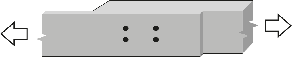
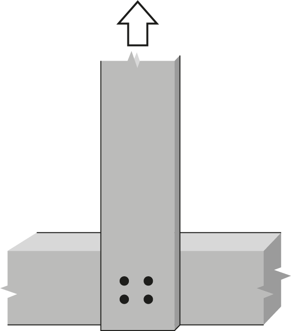
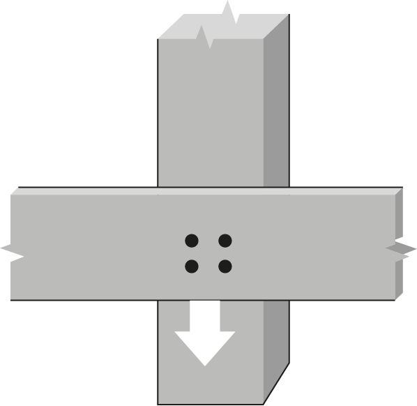
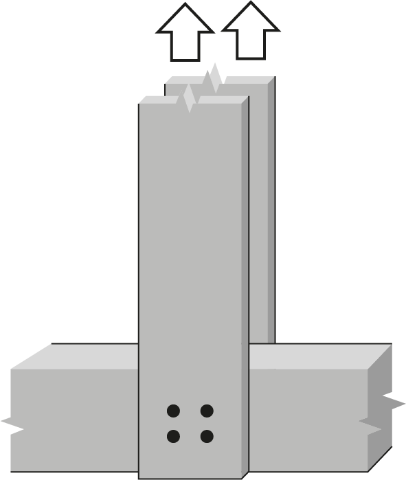
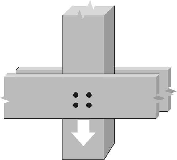
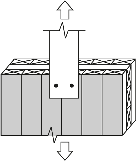
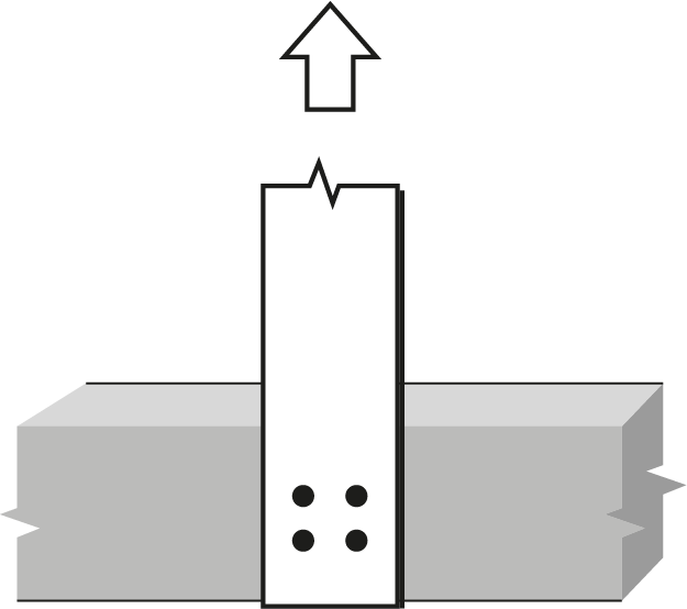
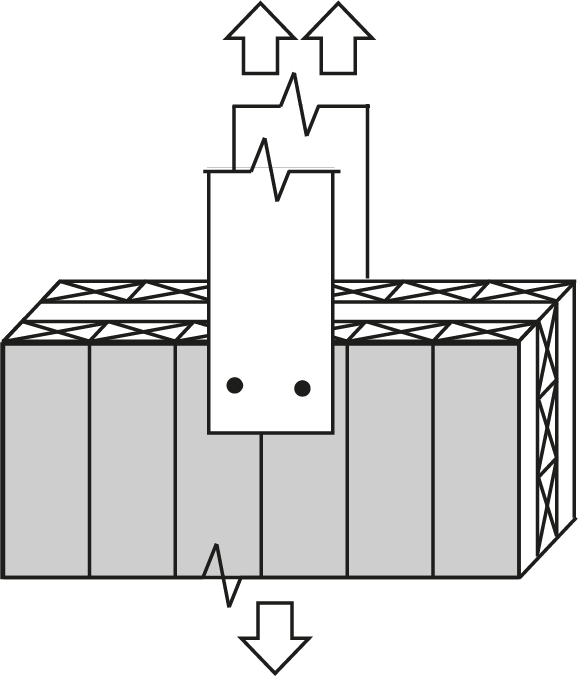
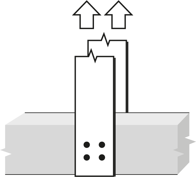
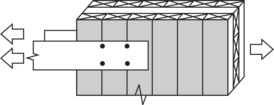
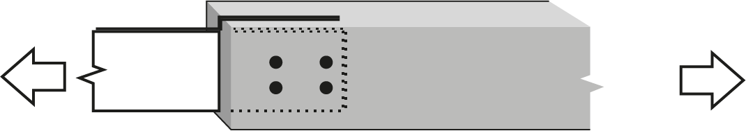
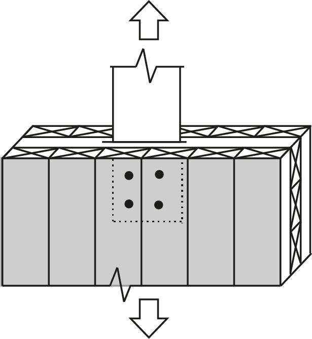
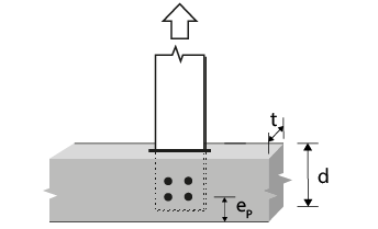
3/4″ Bolt or dowel Single Shear, S-P-F lumber |
 |
|||||||||||||
| Wood Member | Fastener |
 |
|||||||||||||
|
Thickness (mm) |
Depth (mm) |
No. of rows |
 |
No. of fasteners in a row | |||||||||||
| 2 | 3 | ||||||||||||||
 |
|||||||||||||||
|
Side, t₁ |
Main,
t₂ |
Side,
d₁ |
Main,
d₂ |
76 | 114 | 152 | 190 | 229 | 76 | 114 | 152 | 190 | 229 | ||
| 38 | 38 | 89 | 89 | 1 | 0 | 4.74(R) | 7.11(R) | 7.88(f) | 7.88(f) | 7.88(f) | 7.11(R) | 10.7(R) | 11.8(f) | 11.8(f) | 11.8(f) |
| 38 | 38 | 184 | 184 | 2 | 57 | 9.49(R) | 12.4(G) | 14.8(G) | 15.8(f) | 15.8(f) | 12.4(G) | 16.0(G) | 19.5(G) | 23.1(G) | 23.6(f) |
| 38 | 38 | 235 | 235 | 2 | 95 | 9.49(R) | 14.2(R) | 15.8(f) | 15.8(f) | 15.8(f) | 14.2(R) | 21.3(R) | 23.6(f) | 23.6(f) | 23.6(f) |
| 38 | 38 | 286 | 286 | 2 | 133 | 9.49(R) | 14.2(R) | 15.8(f) | 15.8(f) | 15.8(f) | 14.2(R) | 21.3(R) | 23.6(f) | 23.6(f) | 23.6(f) |
| 38 | 38 | 286 | 286 | 3 | 57 | 14.2(R) | 17.7(G) | 20.0(G) | 22.4(G) | 23.6(f) | 17.7(G) | 21.2(G) | 24.8(G) | 28.3(G) | 31.9(G) |
| 38 | 38 | 286 | 286 | 3 | 95 | 14.2(R) | 21.3(R) | 23.6(f) | 23.6(f) | 23.6(f) | 21.3(R) | 32.0(R) | 35.4(f) | 35.4(f) | 35.4(f) |
| 38 | 89 | 89 | 89 | 1 | 0 | 4.74(R) | 7.11(R) | 9.49(R) | 11.9(R) | 13.2(f) | 7.11(R) | 10.7(R) | 14.2(R) | 17.8(R) | 19.2(T) |
| 38 | 89 | 184 | 184 | 2 | 57 | 9.49(R) | 12.4(G) | 14.8(G) | 17.1(G) | 19.5(G) | 12.4(G) | 16.0(G) | 19.5(G) | 23.1(G) | 26.6(G) |
| 38 | 89 | 235 | 235 | 2 | 95 | 9.49(R) | 14.2(R) | 19.0(R) | 22.7(G) | 25.1(G) | 14.2(R) | 21.3(R) | 25.1(G) | 28.6(G) | 32.2(G) |
| 38 | 89 | 286 | 286 | 2 | 133 | 9.49(R) | 14.2(R) | 19.0(R) | 23.7(R) | 26.3(f) | 14.2(R) | 21.3(R) | 28.5(R) | 34.2(G) | 37.8(G) |
| 38 | 89 | 286 | 286 | 3 | 57 | 14.2(R) | 17.7(G) | 20.0(G) | 22.4(G) | 24.8(G) | 17.7(G) | 21.2(G) | 24.8(G) | 28.3(G) | 31.9(G) |
| 38 | 89 | 286 | 286 | 3 | 95 | 14.2(R) | 21.3(R) | 28.5(R) | 33.6(G) | 35.9(G) | 21.3(R) | 32.0(R) | 35.9(G) | 39.5(G) | 41.9(T) |
| 38 | 140 | 140 | 140 | 1 | 0 | 4.74(R) | 7.11(R) | 9.49(R) | 11.9(R) | 14.2(R) | 7.11(R) | 10.7(R) | 14.2(R) | 17.8(R) | 21.3(R) |
| 38 | 140 | 184 | 191 | 2 | 57 | 9.49(R) | 12.4(G) | 14.8(G) | 17.1(G) | 19.5(G) | 12.4(G) | 16.0(G) | 19.5(G) | 23.1(G) | 26.6(G) |
| 38 | 140 | 235 | 241 | 2 | 95 | 9.49(R) | 14.2(R) | 19.0(R) | 22.7(G) | 25.1(G) | 14.2(R) | 21.3(R) | 25.1(G) | 28.6(G) | 32.2(G) |
| 38 | 140 | 286 | 292 | 2 | 133 | 9.49(R) | 14.2(R) | 19.0(R) | 23.7(R) | 28.5(R) | 14.2(R) | 21.3(R) | 28.5(R) | 34.2(G) | 37.8(G) |
| 38 | 140 | 286 | 292 | 3 | 57 | 14.2(R) | 17.7(G) | 20.0(G) | 22.4(G) | 24.8(G) | 17.7(G) | 21.2(G) | 24.8(G) | 28.3(G) | 31.9(G) |
| 38 | 140 | 286 | 292 | 3 | 95 | 14.2(R) | 21.3(R) | 28.5(R) | 33.6(G) | 35.9(G) | 21.3(R) | 32.0(R) | 35.9(G) | 39.5(G) | 41.9(T) |
| 89 | 89 | 89 | 89 | 1 | 0 | 11.1(R) | 16.7(R) | 18.4(f) | 18.4(f) | 18.4(f) | 16.7(R) | 25.0(R) | 27.7(f) | 27.7(f) | 27.7(f) |
| 89 | 89 | 184 | 184 | 2 | 57 | 22.2(R) | 29.0(G) | 34.6(G) | 36.9(f) | 36.9(f) | 29.0(G) | 37.4(G) | 45.7(G) | 54.0(G) | 55.3(f) |
| 89 | 89 | 235 | 235 | 2 | 95 | 22.2(R) | 33.3(R) | 36.9(f) | 36.9(f) | 36.9(f) | 33.3(R) | 50.0(R) | 55.3(f) | 55.3(f) | 55.3(f) |
| 89 | 89 | 286 | 286 | 2 | 133 | 22.2(R) | 33.3(R) | 36.9(f) | 36.9(f) | 36.9(f) | 33.3(R) | 50.0(R) | 55.3(f) | 55.3(f) | 55.3(f) |
| 89 | 89 | 286 | 286 | 3 | 57 | 33.3(R) | 41.4(G) | 47.0(G) | 52.5(G) | 55.3(f) | 41.4(G) | 49.7(G) | 58.1(G) | 66.4(G) | 74.7(G) |
| 89 | 89 | 286 | 286 | 3 | 95 | 33.3(R) | 50.0(R) | 55.3(f) | 55.3(f) | 55.3(f) | 50.0(R) | 75.0(R) | 83.0(f) | 83.0(f) | 83.0(f) |
| 89 | 140 | 140 | 140 | 1 | 0 | 11.1(R) | 16.7(R) | 21.4(d) | 21.4(d) | 21.4(d) | 16.7(R) | 25.0(R) | 32.1(d) | 32.1(d) | 32.1(d) |
| 89 | 140 | 184 | 191 | 2 | 57 | 22.2(R) | 29.0(G) | 34.6(G) | 40.1(G) | 42.8(d) | 29.0(G) | 37.4(G) | 45.7(G) | 54.0(G) | 58.5(T) |
| 89 | 140 | 235 | 241 | 2 | 95 | 22.2(R) | 33.3(R) | 42.8(d) | 42.8(d) | 42.8(d) | 33.3(R) | 48.2(G) | 58.7(G) | 63.4(T) | 63.4(T) |
| 89 | 140 | 286 | 292 | 2 | 133 | 22.2(R) | 33.3(R) | 42.8(d) | 42.8(d) | 42.8(d) | 33.3(R) | 50.0(R) | 64.2(d) | 64.2(d) | 64.2(d) |
| 89 | 140 | 286 | 292 | 3 | 57 | 30.3(G) | 37.2(G) | 44.2(G) | 51.2(G) | 58.1(G) | 37.2(G) | 47.7(G) | 58.1(G) | 66.3(T) | 66.3(T) |
| 89 | 140 | 286 | 292 | 3 | 95 | 33.3(R) | 50.0(R) | 61.4(G) | 64.2(d) | 64.2(d) | 50.0(R) | 64.9(G) | 66.3(T) | 66.3(T) | 66.3(T) |
| 89 | 191 | 140 | 140 | 1 | 0 | 11.1(R) | 16.7(R) | 21.4(d) | 21.4(d) | 21.4(d) | 16.7(R) | 25.0(R) | 32.1(d) | 32.1(d) | 32.1(d) |
| 89 | 191 | 184 | 191 | 2 | 57 | 22.2(R) | 29.0(G) | 34.6(G) | 40.1(G) | 42.8(d) | 29.0(G) | 37.4(G) | 45.7(G) | 54.0(G) | 62.4(G) |
| 89 | 191 | 235 | 241 | 2 | 95 | 22.2(R) | 33.3(R) | 42.8(d) | 42.8(d) | 42.8(d) | 33.3(R) | 50.0(R) | 58.8(G) | 64.2(d) | 64.2(d) |
| 89 | 191 | 286 | 292 | 2 | 133 | 22.2(R) | 33.3(R) | 42.8(d) | 42.8(d) | 42.8(d) | 33.3(R) | 50.0(R) | 64.2(d) | 64.2(d) | 64.2(d) |
| 89 | 191 | 286 | 292 | 3 | 57 | 33.3(R) | 41.4(G) | 47.0(G) | 52.5(G) | 58.1(G) | 41.4(G) | 49.7(G) | 58.1(G) | 66.4(G) | 74.7(G) |
| 89 | 191 | 286 | 292 | 3 | 95 | 33.3(R) | 50.0(R) | 64.2(d) | 64.2(d) | 64.2(d) | 50.0(R) | 75.0(R) | 84.2(G) | 90.5(T) | 90.5(T) |
Notes:
|
. | . | |||||||||||||